
Assembly
Parts Required
Thatcher can be configured for 38 in., 46 in. or 54 in. widths.
Identify Parts: Main Frame
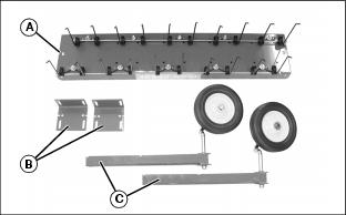
Box of Parts
Bag of Parts
Identify Parts: Frame Extension
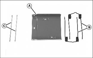
Box of Parts
Bag of Parts
Identify Parts: Mounting Bracket and Lift Lever

Box of Parts
Bag of Parts
Assemble Thatcher Main Frame
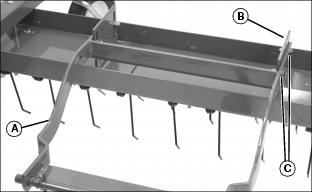
IMPORTANT: Avoid damage! Tips of tines must face direction of forward travel (John Deere label also faces forward). |
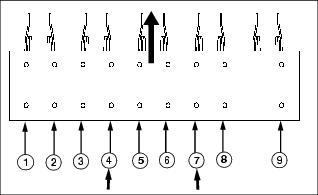
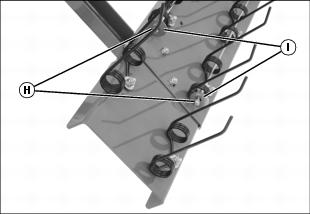
1. Locate frame mounting bracket mounting holes 4 and 7 in main frame.
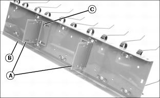
2. Attach frame mounting brackets (A) to main frame (B) using four 5/16 x 1 in. carriage bolts (C) and locknuts. Long side of each bracket must face toward outside of frame as shown. Do not tighten.
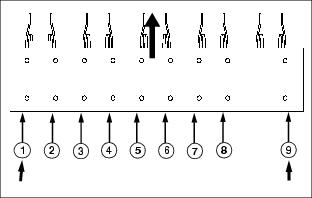
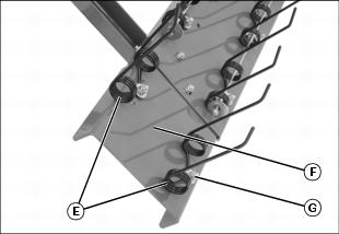
3. Locate wheel support bracket mounting holes 1 and 9 in main frame.
4. Fasten wheel supports (D) to main frame (E) using four 5/16 x 4 in. carriage bolts (F), spacers (G) and locknuts.
46- and 54-Inch Thatcher: Assemble Frame Extensions
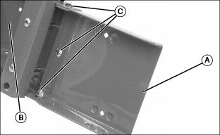
1. Install frame extension (A) on right side of main frame (B) using three 5/16 x 3/4 in. carriage bolts (C), washers and locknuts.
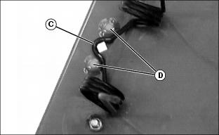
2. Position offset (C) in tine between two extension frame extrusions (D).
3. Attach two tines (E) to extension frame (F) with tine tips facing same direction as tine tips on main frame. Fasten with two 5/16 x 1 in. carriage bolts, washers and locknuts (G).
4. Remove and retain locknuts (H) and washers (I) from main frame tine retention rods.
5. Install two-hole washers (J) onto main retention rods. Fasten with original locknuts (H).
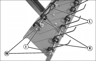
6. Place short retention rods (K) through tines and secure in two-hole washers with 1/4 in. locknuts (L).
7. Install original washers (I) onto other end of short retention rods using 1/4 in. locknuts (M).
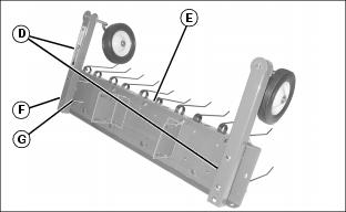
Attach Mounting Frame and Lift Lever Bracket
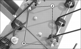
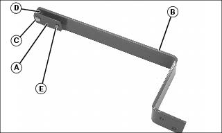
1. Attach mounting frame (A) to frame mounting brackets (B) with four 5/16 x 1 in. carriage bolts (C), washers and locknuts. Do not tighten.
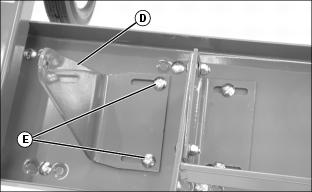
2. Attach lift lever bracket (D) to main frame as shown using two 5/16 x 1 in. carriage bolts (E) and locknuts. Do not tighten.
Assemble Lift Lever Components
1. Install retainer strap (A) on lift lock extension (B) using 5/16 x 1-1/2 in. carriage bolt (C), spacer (D) and locknut.
2. Install 5/16 x 1-1/4 in. drilled pin (E) through retainer and lift lever. Secure with quick-release pin.
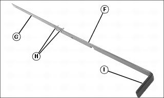
3. Join upper lift lever (F) and lower lift lever (G) as shown using two 5/16 x 1 in. carriage bolts (H) and locknuts.
NOTE: Warm the handle grip until flexible for easier installation.


