
Assembly
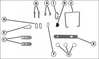
Parts in Kit
Parts in Bag
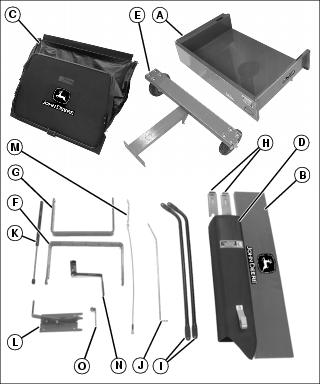
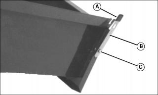
Identify POWER FLOW Chute Parts
Install Dump Cart Latch Bracket
NOTE: Tip cart box on end for ease of installation.
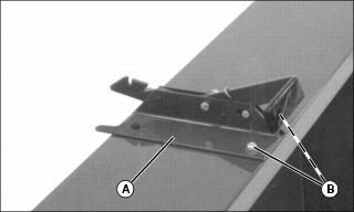
1. Place dump cart latch bracket (A) on front of cart box and fasten top of bracket with two 5/16x3/4 in. hex head bolts and 5/16 in. lock nuts (B). Do not tighten.
Install Drawbar Assembly
NOTE: Lay cart box upside-down for ease of installation.
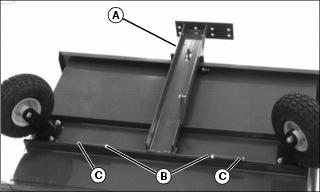
1. Attach drawbar assembly (A) to cart box with two 3/8x4-1/2 in. hex head bolts (B) and 3/8 in. lock nuts (C).
2. Do not overtighten. Drawbar must pivot freely.
Install Gas Cylinder Bracket
NOTE: Tip cart box on end for ease of installation.
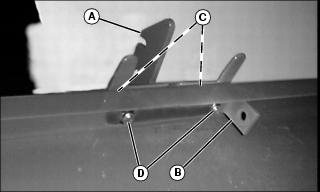
1. Install lift cylinder bracket (B) on cart box using two 5/16x3/4 in. hex head bolts (C) and 5/16 in. lock nuts (D).
2. Align lift bracket with drawbar and tighten all four nuts to secure lift bracket and gas cylinder bracket.
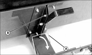
Install Latch On Drawbar
NOTE: If dump cart latch does not lock in place when pushing down on cart box, adjust dump cart latch. (See Adjusting Dump Cart Latch in this section.)

1. Install latch (A) in holes (B) on drawbar.
2. Push latch to the rear and hook in slot in dump cart latch.
Adjusting Dump Cart Latch
2. Loosen lock nut (B). Move bolt in slot until latch locks in place.
Install Preloaded Gas Cylinder
NOTE: Tip cart box on end and open for ease of installation.
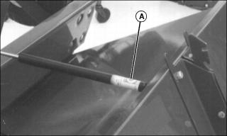
1. Install barrel end of gas cylinder (A) on ball joint closest to cart box.
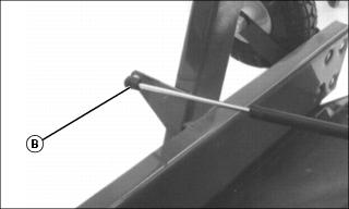
2. Install rod end of gas cylinder (B) on ball joint closest to wheel assembly.
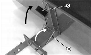
3. Push down on drawbar and latch lift lever bracket (C) to locked position.
4. Push latch (D) into notch in lift lever bracket to locked position.
Assemble Quik-Tatch Bracket
NOTE: Be sure to use wide Quik-Tatch bracket. Narrow Quik-Tatch bracket is not used in this application.

1. Attach slide plates (A) to outside of quik-tatch bracket (B) with 5/16x1-1/2 in. carriage bolt (C), 5/16 in. washer (D), spring (E), 5/16 washer (D) and 5/16 in. lock nut (F).
2. Tighten lock nut so that one thread of carriage bolt extends past nut.
Attach Quik-Tatch Bracket Assembly To Drawbar Assembly
NOTE: X475 AWS tractor uses different mounting holes than other models.
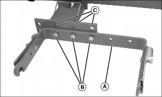
Attach quik-tatch bracket (A) to drawbar with three 1/2x1-1/4 in. hex head bolts, 1/2 in. lock washers and 1/2 in. nuts (B).
• X475 AWS tractor: Use top holes in drawbar (C).
• All others: Install in lower holes as shown.
Assemble Tailgate
NOTE: Do not install tailgate when using cover.
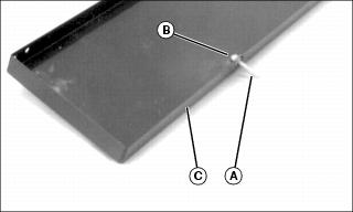
1. Install two tailgate pins (A), lock washers and hex nuts (B) in tailgate (C) at dimpled holes.
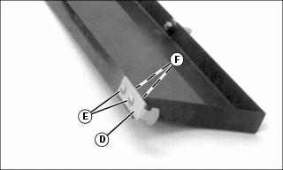
2. Install one latch (D) on each side of tailgate using two 1/4x1/2 in. round head screws (E), 1/4 in. lock washers and 1/4 in. hex nuts (F). Hand tighten.

3. Insert tailgate pins (G) into holes in cart box.

4. Put latches (I) in slots (H) on dump cart. Tighten all hardware.
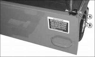
Install Locking Latch To Cart
NOTE: Bolt goes through hole closest to top of cart and tab on latch goes in bottom hole on cart.
1. Install vinyl cap (A) on latch.
2. Install locking latch (B) on cart using 5/16x3/4 in. hex head bolt, and 5/16 in. lock nut (C). Hand tighten.
Assemble Cover
NOTE: For ease of installation place bagger on its side.
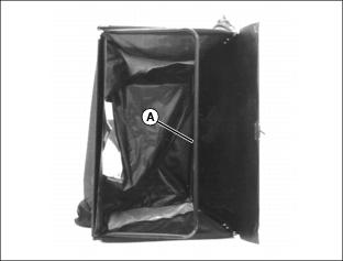
1. Push front support rod (A) to the inside of cover.
Picture Note: Left Side Shown.
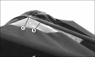
2. Install one end of side support tubing (B) on front cover support.
NOTE: Make sure bolt goes through mesh material (under cover flap) and support rod under cover. Put lock nut to inside of cover.
3. Fasten with 1/4x1-1/2 in. carriage bolt (C) and 1/4 in. lock nut.
NOTE: Do not overtighten. Must pivot freely to collapse cover.
NOTE: It may be necessary to tighten nut (F) to allow installation of spring locking ring (D).
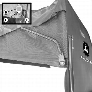
Picture Note: Left Side Shown.
5. Install other end of side support tubing on stud (E) and fasten with spring locking ring (D).
6. Repeat Steps 2–5 for other side of front cover.
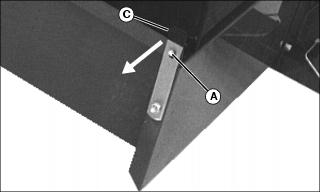
Install Cover Latch Bracket
NOTE: Make sure bolt goes through frame and slits in cover. Put lock nuts to the inside of cover.
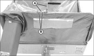
Install lift bracket (A) on cover using two 1/4x1-1/2 in. carriage bolts and 1/4 in. lock nuts (B).
Install Cover Latch Rod
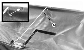
1. Install end of cover latch rod (A) with two bends through hole in cover and hole in cover support tube.
2. Put end of cover latch rod (A) with one bend in center hole on cover latch bracket (B).
3. Put washer (C) on cover latch rod and fasten with locking ring (D).
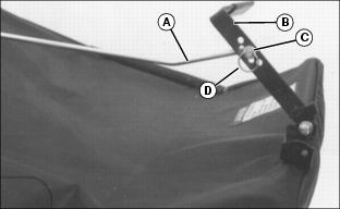
Install Cover
NOTE: Do not install tailgate on cart when using cover.
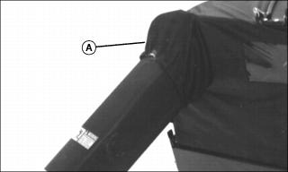
1. Put pivot rod (A) through hole on left corner of cart box flange (B).
2. Pull cover attaching latch (C) outward.
3. Slide pivot rod (A) in slot and release latch. Tighten hardware.

4. Push cover down so bracket (D) fits over dump cart box flange.
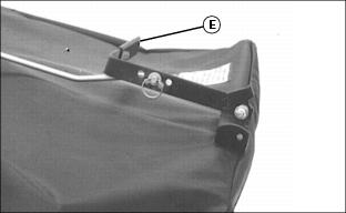
5. Push cover latch bracket (E) rearward to latch cover at rear of cart box.
Install Cover Chute
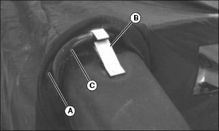
1. Push cover (A) back and slide clip (B) located on cover chute over front cover support (C) until clip snaps in place.
2. Pull cover (A) over cover chute.
Attach Cable To Lift Bracket
IMPORTANT: Avoid damage! To prevent damage to cart, do not operate unit before installing cable assembly. |

1. Find chain link that is approximately 69 cm (27 in.) from opposite end of cable. Put quick link (A) through that chain link.
2. Put quick link in hole on lift bracket (B), and tighten nut on quick link.
Cut POWER FLOW Chute and Install Strap
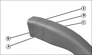
1. Cut chute at groove indicated by letter in table below:
2. Drill a 5 mm (3/16 in.) hole through dimple mark indicated by letter in table below:
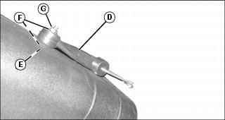
3. Attach chute strap (D) to top of chute with screw (E) and washer (F) (from inside chute), second washer (F) and locknut (G).