
Operating
Daily Operating Checklist
o Remove grass and debris from machine.
o Check area below machine for leaks.
Avoid Damage to Plastic and Painted Surfaces
· Do not wipe plastic parts unless rinsed first.
· Insect repellent spray may damage plastic and painted surfaces. Do not spray insect repellent near machine.
· Be careful not to spill fuel on machine. Fuel may damage surface. Wipe up spilled fuel immediately.
· Prolonged exposure to sunlight will damage the hood surface.
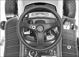
Operator Station Controls
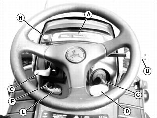
E - Implement (Mower Deck) Lift Lock Lever
H - Reverse Implement Option (RIO) Button
A - Implement (Mower Deck) Lift Lock Lever
C - Implement (Mower Deck) Lift Pedal
Miscellaneous Controls
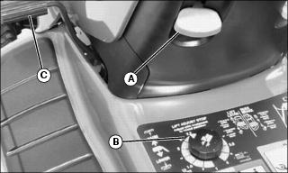
Adjusting Seat
To adjust seat position:
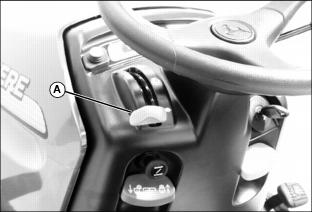
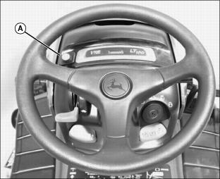
1. Pull lever (A) up, out of locked position.
2. Slide seat forward or rearward to desired position.
To adjust seat for ride comfort:
Lift seat, unscrew and move springs to desired position as follows:
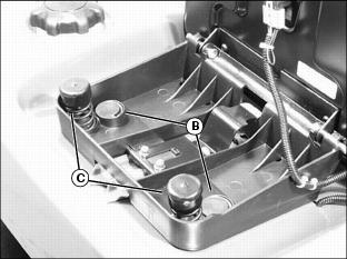
· Install both springs into front position (B) for softest ride.
· Install both springs into rear position (C) for firm ride.
· Install springs in all four positions (B and C) for the firmest ride.
NOTE: Additional springs are available at your John Deere dealer.
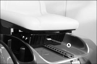
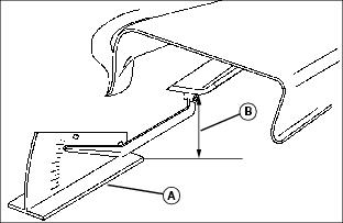
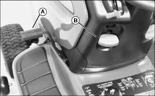
Adjusting Cutting Height
NOTE: Mower deck should be raised to highest (transport) position before turning cutting height knob.
Cutting height can be adjusted from approximately 25-102 mm (1-4 in). When mower deck is raised to highest (transport) position, cutting height is approximately 102 mm (4 in).
1. Check tire pressure and adjust as needed.
2. Push lift pedal (A) to raise mower deck to highest (transport) position.
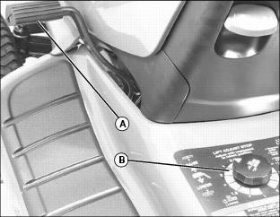
3. Turn mower cutting height knob (B) to desired cutting height. Mower will be at that approximate cutting height when it is lowered.
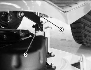
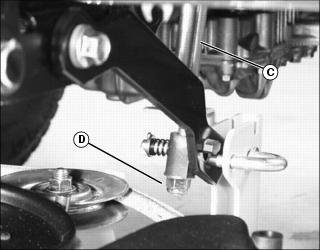
5. Check that the actual height of cut matches the reading on the cutting height knob. If they do not match, adjust lift links (C) on both sides of mower.
· Turn nuts (D) on both sides clockwise to raise the mower deck to match the cutting height knob.
· Turn nuts (D) on both sides counterclockwise to lower the mower deck to match the cutting height knob.
6. Check side-to-side mower level.
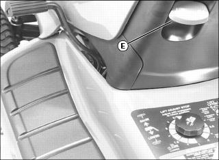
8. Raise mower deck to highest (transport) position and pull up lever (E) to lock deck.
9. If lever does not lock, lower the mower deck, and adjust lift links (C).
a. Turn nuts (D) on both sides one turn counterclockwise to lower the mower deck.
b. Check that lever locks when mower deck is in the transport position.
c. Repeat until lever locks in highest (transport) position.
Adjusting Mower Deck Wheels
1. Park machine safely on level surface.
2. Inflate tires to correct pressure.
3. Raise mower deck to transport (highest) position and adjust cutting height.
4. Lower mower deck to mowing position.
NOTE: Bottom of wheels should be approximately 3-13 mm (1/8-1/2 in.) from the ground.
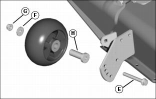
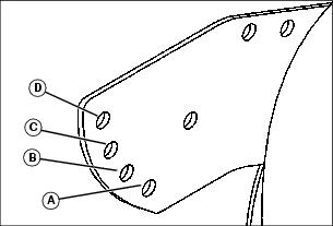
5. Check mower wheel position. Remove bolt (E), washer (F), and nut (G) on all wheels and move wheel with bushing (H) to proper hole.
6. Install bolts and nuts and tighten to specification.
Specifications:
Adjusting Mower Level (Side-to-Side)
NOTE: Mower wheels should not contact the ground when leveling the deck.
1. Park machine safely on level surface.
2. Inflate tires to correct pressure.
3. Adjust cutting height to 51 mm (2 in).
NOTE: The difference between blade measurements must not be more than 3 mm (1/8 in).
Picture Note: A convenient leveling gauge (A) is available from your John Deere dealer.
5. Position mower blades as follows and measure from each outside blade tip (B) to the level surface:
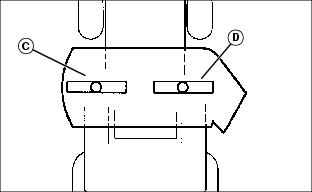
· 38-Inch, 42C and 48C mowers:
Turn left blade (C) and right blade (D) as shown. Take measurement for both blades.
Picture Note: Underside of deck shown.
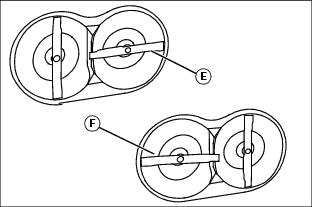
Turn blade (E) as shown. Take measurement. Rotate blades 90° so that blade (F) is positioned as shown. Take measurement.
NOTE: Mower deck's cutting height may need to be adjusted to match mower height control knob setting.

6. Adjust lift links (G) on both sides of mower by turning nut (H) clockwise to raise side of mower, counterclockwise to lower side of mower.
NOTE: Deck will not lock in transport position if adjusted too high.
7. If lift latch handle does not lock, lower the mower deck, and turn nut (H) on each side of deck one turn counterclockwise to lower the deck.
8. Check if latch handle is locked and repeat step until latch handle locks in transport (highest) position.
Adjusting Mower Level (Front-to-Rear)
NOTE: Mower wheels should not contact the ground (level surface) during leveling.
1. Park machine safely on level surface.
2. Inflate tires to correct pressure.
3. Adjust cutting height to 51 mm (2 in).
NOTE: You need to measure only one blade.
5. Turn blade so tip points straight forward.
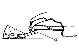
Picture Note: A convenient leveling gauge is available from your John Deere dealer.
6. Measure the distance (A) from blade tip to the ground (level surface):
The front blade tip must be 3-6 mm (1/8-1/4 in.) lower than rear blade tip.
The difference between front and rear blade tip measurements must not be more than 3 mm (1/8 in).
7. Turn front adjuster nut (B) clockwise to raise front of mower deck or counterclockwise to lower front of mower deck.
8. Measure blade tip again and adjust if necessary.
Testing Safety Systems
Use the following checkout procedure to check for normal operation of machine.
If there is a malfunction during one of these procedures, Do not operate machine. See your John Deere dealer for service.
Perform these tests in a clear open area. Keep bystanders away.
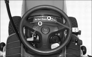
Testing Mower Engagement Lever Switch
1. Park machine safely. (See Parking Safely in the Safety section.)
4. Push mower engagement lever (A) forward to engage.
Testing Seat Switch
1. Park machine safely. (See Parking Safely in the Safety section.)
4. Pull mower engagement lever (A) back to disengage.
5. Start engine and move throttle lever (B) to half-speed position.
6. Push mower engagement lever (A) forward to engage.
7. Move throttle lever (B) to fast speed position.
8. Raise up off of seat, but do not get off tractor.
Testing Park Brake Switch
1. Park machine safely. (See Parking Safely in the Safety section.)
4. Pull mower engagement lever (B) back to disengage.
Testing Brake Pedal Switch
3. Pull mower engagement lever (A) back to disengage.
4. Start engine and move throttle lever (B) to fast speed position.
5. Release brake pedal slowly.
6. Raise up off of seat, but do not get off tractor.
Testing Park Brake
1. Park machine safely. (See Parking Safely in the Safety section.)
3. Put transmission in N (neutral) on units with manual transmission.
4. Engage free-wheeling lever on units with automatic transmission.
5. Try to push machine manually.
Testing Reverse Implement Option (RIO)
1. Park machine safely. (See Parking Safely in the Safety section.)
3. Engage PTO to start attachment.
Before backing up, carefully check the area around the machine. |
4. Look behind the vehicle to be sure there are no bystanders.
5. Begin reverse travel by depressing reverse foot pedal for automatic transmission or moving gear shift lever to R (reverse) position for gear transmission.
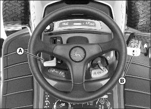
Using Park Brake
Always lock the park brake and remove the key before leaving the machine unattended. |
Locking park brake:
1. Push and hold brake pedal (A) down.
2. Pull park brake lever (B) up to lock park brake.
3. Release brake pedal. Pedal should stay down and park brake lever should stay locked.
Unlocking park brake:
1. Push and hold brake pedal down.
2. Push park brake lever down to unlock park brake.
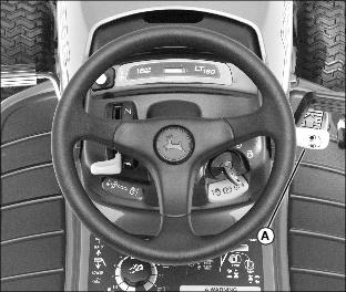
Starting Engine
NOTE: Engine will not start unless mower is disengaged and transmission is in neutral.
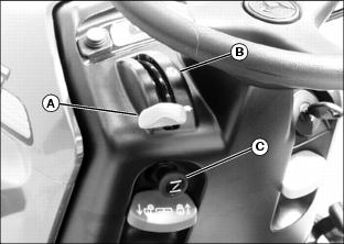
Move throttle lever (A) to the half-speed position (B) and pull out choke knob (C). Gradually push in choke knob after the engine starts and warms up.
Pull out choke knob (C). Push choke knob in as soon as the engine starts.
IMPORTANT: Avoid damage! Starter may be damaged if starter is operated for more than 20 seconds at a time: · Wait two minutes before trying again if engine does not start. |
3. Turn key to start position (C) for no longer than five seconds.
4. Release key to run position (D) when engine starts.
· If engine does not start, wait 10 seconds.
· Turn key to start position again for no longer than 5 seconds.
· Repeat procedure if necessary.
IMPORTANT: Avoid damage! Unnecessary engine idling may cause engine damage. Excessive idling can cause engine overheating, carbon build-up, and poor performance. |
5. Let engine run at half-speed position for a couple of minutes to warm up before operating machine.
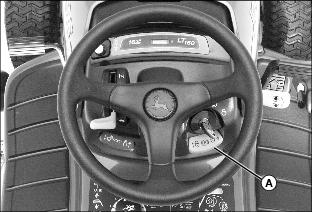
Stopping Engine
1. Move throttle lever (A) to slow position and let engine run at low throttle for a few seconds.
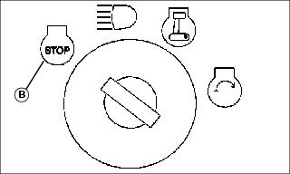
2. Turn key to STOP position (B). Engine will stop and headlights will turn off.
Using Headlights
NOTE: Headlights will drain the battery rapidly if key switch is left in headlights position (B) without the engine running.
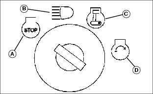
Turning Headlights On/Off (with Engine Off)
Turn key switch to Headlights On Position (B). However, leaving key in this position will rapidly drain battery. Turn headlights off after 1-2 minutes.
Turn key switch to STOP Position (A).
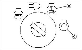
Turning Headlights On/Off (With Engine On)
Start engine. Turn key switch from Run Position (C) to Headlights On Position (B).
Turn key switch from Headlights On Position (B) to Run Position (C). Lights will turn off but engine will continue to run.
Turn key switch from Headlights On Position (B) to STOP Position (A). Lights and engine will turn off.
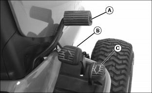
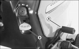
Using Travel Pedals
To travel forward:
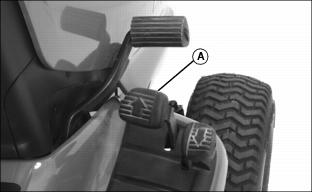
1. Push down the forward travel pedal (A).
To travel in reverse:
NOTE: When you push the reverse pedal, the engine and mower will stop if the mower engagement lever is in the on position.
1. Pull mower engagement lever to off position.
2. Look behind the machine to be sure there are no bystanders nearby.
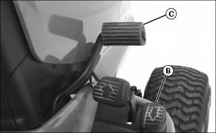
3. Push down the reverse travel pedal (B).
To stop travel:
Push down brake pedal (C). Travel pedals will return to the neutral position.
Using Reverse Implement Option (RIO)
Before backing up, carefully check the area around the machine. |
NOTE: Backing up while the mower is engaged is strongly discouraged.
The Reverse Implement Option should be used only when operating another implement (attachment) or when the operator deems it necessary to reposition the machine with the mower engaged.
2. Look behind the vehicle to be sure there are no bystanders.
3. Push and hold in the reverse implement button (A) while depressing reverse foot pedal.
NOTE: If the engine and mower stop while repositioning the machine, return the mower engagement lever to the off position. Start engine and engage mower. Begin again with step 2.
4. As the machine begins to move backward, release the reverse implement button and reposition the machine.
5. Resume forward travel. The implement (attachment) should continue operating.
6. Repeat procedure to position the machine again.
Using Mower Lift Pedal
Raising Mower Deck:
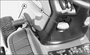
1. Push down and hold lift pedal (A).
2. Pull up lever (B) to lock mower deck in the transport position.
3. Release lift pedal. Pedal should stay down and lever should stay locked.
Lowering Mower Deck:
1. Push down and hold lift pedal (A).
2. Push down lever (B) to unlock.
3. Release lift pedal to lower mower deck to the set cutting height.
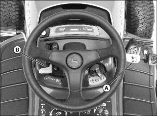
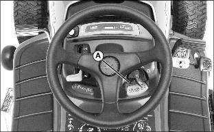
Using Mower
1. Start engine and run at half-speed position for a couple of minutes to warm up.
4. Push throttle lever (A) to full throttle position.
5. Push mower engagement lever (B) forward to start mower.
IMPORTANT: Avoid damage! The mower engagement lever is spring-assisted. Damage may occur to the lever components if the lever snaps back when disengaging. Hold firmly onto the lever when disengaging. |
NOTE: Mower and engine will stop if you press reverse pedal while mower is engaged.
6. Pull lever (B) back to stop mower blades.
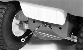
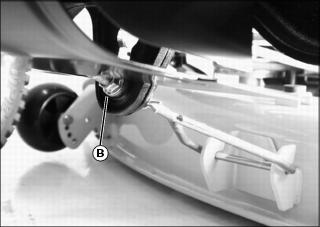
Pushing Machine (Using Free-Wheeling Lever)
IMPORTANT: Avoid damage! Transmission damage may occur if the machine is towed or moved incorrectly: |
2. For gear transmission, put transmission in N (neutral).
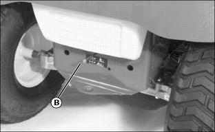
3. Pull out free-wheeling lever (B) at rear of machine.
4. Push machine to desired location.
5. Push in free-wheeling lever.
Transporting Machine on Trailer
Be sure trailer has all the necessary lights and signs required by law.
· Park trailer on a level surface. · Use of a trailer with sides is recommended. |
IMPORTANT: Avoid damage! Transmission damage may occur if the machine is towed or moved incorrectly: |
1. Park trailer on level surface.
2. Drive machine onto heavy-duty trailer.
3. Lower mower to trailer deck.
5. Turn off machine and remove key.
6. Fasten lawn tractor to trailer with heavy-duty straps, chains, or cables. Both front and rear straps must be directed down and outward from tractor.
Using Wheel Weights
· Install front wheel weights for added stability and steering control when you use equipment such as the rear-mounted grass bagger.
· Install rear wheel weights when using the front blade.
· Remove wheel weights when not required.
Installing Tire Chains
IMPORTANT: Avoid damage! Loose tire chains can cause machine damage. Periodically check chain tightness and adjust as necessary. |
NOTE: Chains are available from your John Deere dealer.
1. Park machine safely. (See Parking Safely in the Safety Section.)
2. Lay chains out flat with the cross chain hook ends facing downward.
3. Remove any twists and tangles from cross chain and rim chain.
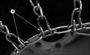
5. Drape chain over tire with the lever fastener on outside of tire and cross link hooks (A) facing upward and away from tire.
6. Adjust chain for straightness and an even amount of cross chain links on each side of tire.
7. Place the first cross chain (opposite the end with fastener and inside hook) under tire.
8. Pull the inside rim chain tight and hook the inside hook.
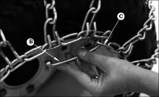
9. Pull the outside rim chain tight and hook the outside lever fastener (B) by running the end through a free link (C).
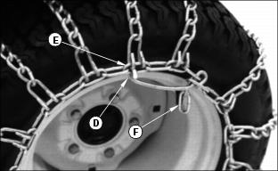
10. Close the fastener by rotating it back 180 degrees and engaging the hook (D) on the end of the fastener into a rim chain link (E).
Make sure the chain is centered on the tire with approximately the same number of free rim links (F) on the inside and outside.
NOTE: The chain should be as tight as possible. If chain is loose, unhook the fastener and pull chain tight again.
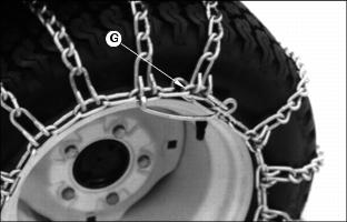
11. Tie excess rim chain links (G) back to the rim chain.
12. Drive forward on chains 912 m (3040 ft.) and recheck for tightness. Adjust as necessary.
Mowing Tips
The following recommendations will produce the best lawn cut quality and appearance:
· Keep mower blades sharp. Dull blades will tear grass; tips of grass will then turn brown.
· Cutting grass too short may kill grass and let weeds grow easily. The suggested finished cut height range is 44 to 70 mm (1.75 to 2.75 in.).
· Adjust cutting height to remove only 1/3 of the grass at a time.
· Do not mow wet grass. Wet cutting conditions will not adversely affect the cutting performance of the Freedom42 Mulching Mower.
· Mow grass often. Short grass clippings will decay quickly.
· Mow with engine at full throttle.
· Adjust travel speed to match mowing conditions:
· Travel at slow speed when you mow thick, tall grass, make sharp turns or trim around objects.
· Travel at moderate speed when you mow thin grass.
· Use a different mowing pattern each time you mow. Overlap mowing paths 50 to 100 mm (2 to 4 in.).
· Drive over ridges and through shallow ditches straight-on, not at an angle.
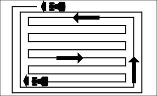
· When using the Freedom42 deck: Mow around the outside twice, then mow inside in straight passes. Best cut is achieved when mowing in a straight line.
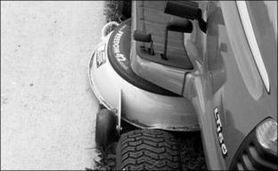
· When mulching near pavement, overlap the pavement by 50 mm (2 in.) to allow clippings to dispense over grass.
· A thick layer of mulched leave can prevent sunlight from getting to grass and smother it. Taller grass heights allow mulched leaves to dispense easier in lawn. Mulch leaves several times if needed.
· Use a thatcher in late spring or summer to pull up dead grass and aerate ground.