
Assembly
Identify Parts
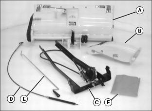
Bag of Parts (F) Contains:
Attaching Parts Carton Contains:
Front Lift Kit
LX280AWS Only: Parts Obtained From a John Deere Dealer:
Assemble Lift Bar
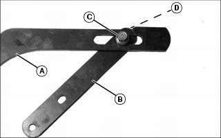
Attach lift bar (A) to foot lift bracket (B) with shoulder bolt (C). Be sure shoulder bolt rides in the slot of lift bar. Secure with M10 locknut (D).
Assemble Chute and Welded Frame
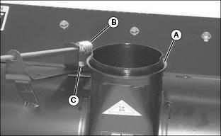
1. Apply grease on chute base (A) and worm gear (B).
2. Loosen nut (C) and move worm gear bracket away from chute base.
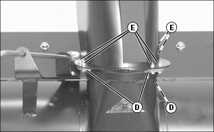
3. Fasten chute to base with three clips (D) and six M5x20 bolts and locknuts (E).
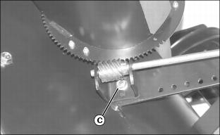
4. Move worm gear against teeth on discharge chute and tighten nut (C).
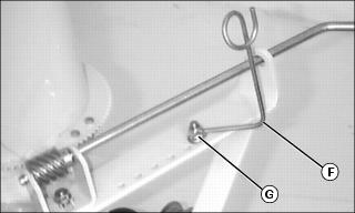
5. Install cable guide (F) on crank support using M8x25 bolt and lock nut (G).

6. Install idler sheave (H) and belt guide (I) to welded support (J) using M10x50 bolt (K) and flange locknut (L). Do not tighten.
IMPORTANT: Avoid damage! Make sure belt does not touch belt guide. After tightening nut, idler sheave must rotate freely when not in contact with belt. |

7. Slide welded frame to snowthrower and attach belt to drive sheave (M) and between idler sheave (H) and belt guide (I). Tighten nut (L).
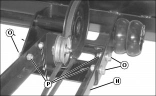
8. Lift up on welded frame (N) near sheaves and fasten to snowthrower frame with four M12x30 hex flange bolts (O) and M12 locknuts (P), (nuts on inside).
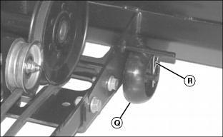
9. Remove wheels (Q) from storage position and install one on each side of snowthrower frame. Fasten with quick-release pin (R).
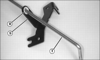
10. Slide chute and spout control bracket (S) onto chute control rod (T). With wider flange facing toward handle, slide snap-in bearing (U) over chute control rod and insert snap-in bearing into bracket.
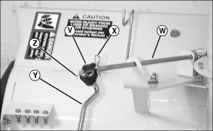
11. Install black U-joint (V) to crank support rod (W) and fasten with small quick-release pin (X).
12. Insert end of chute control rod (Y) into U-joint and fasten with small quick-release pin (Z).
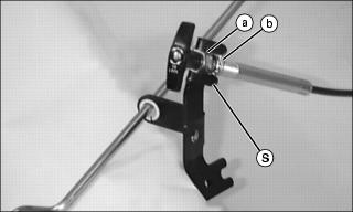
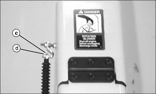
13. Thread top nut (a) on cable as far as possible.
NOTE: Handle must be in vertical position when tightened to allow proper operation.
14. Put handle end of cable into top slot of chute and spout control bracket (S) with lock washer and nut (b) against bottom side of bracket.
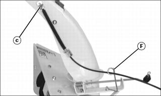
15. Route spout control cable end (c) through cable guide (F).
NOTE: Aim spout upward and pull cable end so that cable is fully extended before installing cable on spout bracket.
16. Install cable end (c) into upper spout bracket hole and fasten with #10 hex nut (d).
NOTE: Star washers (g) are on both sides of lower spout bracket (f).
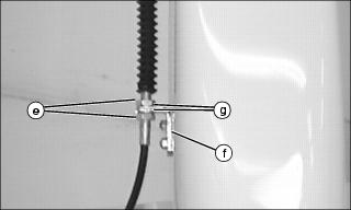
17. Loosen nuts (e). Install cable assembly into lower spout bracket (f). Tighten nuts.
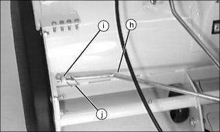
18. Install sway bar (h) on welded rod (i) and secure with large spring locking pin (j).
NOTE: LX280AWS only: Install yokes in first hole (o) in snowthrower frame.
All other Models: Install yokes in second hole (p) in snowthrower frame.
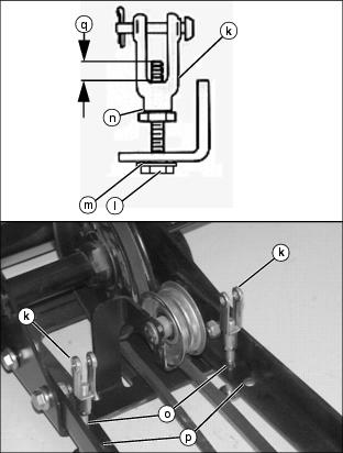
19. Fasten each yoke (k) to hole snowthrower frame with 3/8x2 in. bolt (l), 0.406x1x0.134 in. washer (m) and 3/8 in. jam nut (n).
20. Adjust jam nuts until bolt exposed inside of yoke, dimension (q), is approximately 5 7 mm (3/16 - 9/32 in.).