
Installing Attachment
Install Ballast
Install the proper front ballast to help counter-balance the total weight of the snowthrower. Remove ballast when the snowthrower is removed. This will ensure proper operation of the machine when not removing snow.
NOTE: LX280-AWS Only: Mounting Kit (BM19797) is required to install Rear Weight Bracket and Mounting Kit (BM19211) is required to install Tractor Trunk.
• Two 19 kg (42 lb) Rear Suitcase Weights, or
• Tractor Trunk with 45.4 kg (100 lb) of ballast
• GT Series and GX255 Required Ballast:
• One 19 kg (42 lb) Rear Suitcase Weight, or
• Tractor Trunk with 19 kg (42 lb) of ballast, or
• GT Series and GX255 Recommended Ballast:
• Four 19 kg (42 lb) Rear Suitcase Weights, or
• Tractor Trunk with 68 kg (150 lb) of ballast, or
Installing Front Brackets (LX280AWS)
NOTE: LX280AWS does not have D-shaped holes in front brackets.
1. Park machine safely. (See Parking Safely in Safety section.)
NOTE: LX280AWS: Obtain brackets and bolts from a John Deere dealer.
2. Install front brackets on front of machine frame.
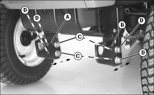
• LX280AWS: Right bracket (A) must be on inside of machine frame. Left bracket (B) must be on outside of machine frame.
NOTE: LX280AWS: Bolts (C) are hex.
3. Fasten each bracket with two M12x30 hex head bolts (C) and two M12 hex flange locknuts (D).
• LX280AWS Only: Bolt heads must be on outside.
4. Move brackets so that bottom is level with machine frame. Tighten nuts.
Installing Manual Lift Assembly
1. Slide left side of front lift shaft (A) and then right side into D-shaped holes of front brackets (B).
2. Slide D-shaped bearings (C) onto each front bracket.
3. Secure right side with medium quick-release pin (D).

4. Install welded lift arm (E) onto left side of front lift shaft. Fasten with long drilled pin (F) and small quick-release pin (G).
Installing Lift Bar Assembly
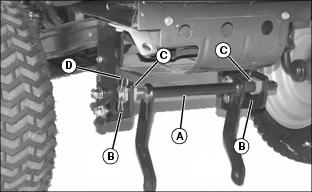
1. Attach lift bar assembly (A) to lift pedal (B) with two M10x30 flange bolts (C) and M10 flange locknuts.
2. Attach opposite end of lift bar assembly:
Picture Note: LX280 with all-wheel steer shown.
• For LX280 machines with all-wheel steering, install lift extension bracket (D) onto outer front end of lift bar (E) so it is level with machine frame, as shown. Secure with M10x30 flange bolt (F) and M10 flange locknut. Tighten locknut to 80 N•m (59 lb-ft).
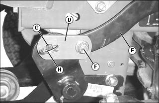
Slide end of lift extension bracket (D) onto end of welded lift shaft arm pin (G). Secure with locking ring (H).
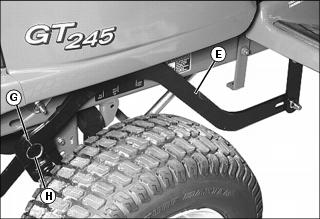
• For all other machines, slide end of lift bar (E) onto end of welded lift shaft arm pin (G). Secure with locking ring (H).
Installing Snowthrower
Keep hands and arms from under attachment when in the raised position. |
1. Align machine with snowthrower frame.
2. Stop engine and lock park brake.
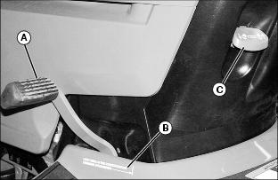
3. Pull lift pedal (A) back by hand to lower lift assembly to the lower/down position (B). Pull lock lever (C) up to lock lift assembly in the lowered position.
4. Install snowthrower latching mechanism.
• Remove drilled pin from C-shaped latch in snowthrower frame and let latch swing open.
• Slide snowthrower frame under machine.
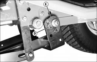
• Remove small spring locking pin (D) and C-shaped latch (E), from left side only, to allow easy installation of blade frame.
• Attach both sides of rear blade frame to draft arm pivot bolts.
• Reinstall C-shaped latch (E) and small spring locking pin (D) to left side.
NOTE: Make sure latch pivots freely. Use two extra washers from Bag of Parts if C-shaped latch (E) does not pivot freely when frame is pulled to one side.
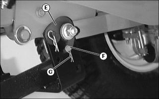
• Secure C-shaped latch (E) with drilled pin (F) and small spring locking pin (G), on both sides.
5. Pivot belt tightener lever (G) to the rear to loosen belt.
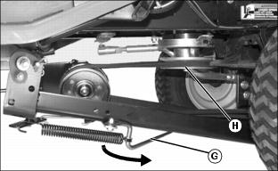
6. Install belt on machine drive sheave (H).
7. Pivot tightening lever (G) forward and lock under snowthrower frame to tighten belt.
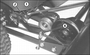
9. Fasten sway bar (I) to sway bar bracket with large quick-release pin (J).
NOTE: Install heads of slotted drilled pins (K) to the outside of lift arms.
10. Fasten two yokes (K) to front lift shaft with slotted drilled pin and small quick-release pin.
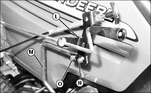
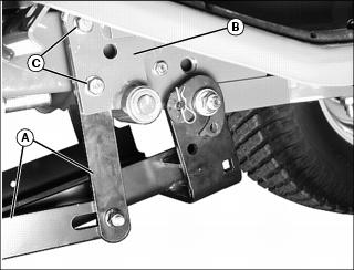
11. Attach 3/8x1 in. hex flange screw (O) and 3/8 in. flange nut in second hole of support rod (M) and hook end of bracket (L) over screw.
• Install M8x25 flange bolt (N) and M8 flanged locknut in first hole to secure bracket.
NOTE: If Snowthrower cannot be locked in up position, decrease snowthrower lift height.
12. Pull up slightly on foot pedal and push down on lock lever to unlock latch; push foot pedal all the way down (towards front of machine), and pull up on lock lever to lock snowthrower into raised position.
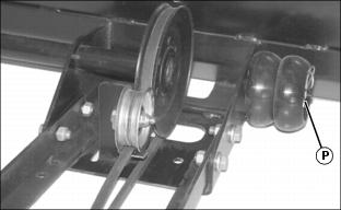
13. Move wheels to storage position and secure with original quick-release pins (P).