
Operating
Daily Operating Checklist
o Check transmission oil level.
o Check coolant level on liquid cooled engine.
o Remove grass and debris from machine.
o Check area below machine for leaks.
Avoid Damage to Plastic and Painted Surfaces
· Do not wipe plastic parts unless rinsed first.
· Insect repellent spray may damage plastic and painted surfaces. Do not spray insect repellent near machine.
· Be careful not to spill fuel on machine. Fuel may damage surface. Wipe up spilled fuel immediately.
Operator Controls
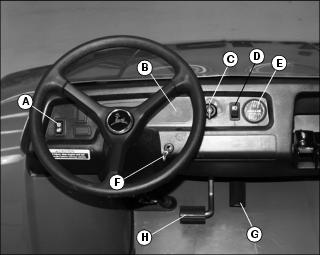
Miscellaneous Controls
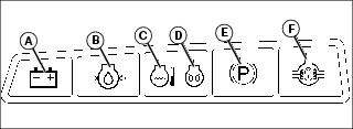
Indicator Panel
NOTE: Only one indicator bulb illuminates both Coolant Temperature (C) and Engine Preheat (D) Indicators at the same time.
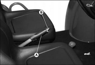
Using Hand Holds
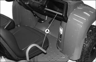
Hand holds (A) are provided for passenger balance when driving over rough terrain. Use dash bar and side rails on seats for stability.
Adjusting Seats
1. Lift and tip vehicle seat forward.
NOTE: The back of the seat will hit the front of the fender. Use care when adjusting.
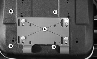
Picture Note: Operator seat shown.
3. Slide seat forward or rearward to desired position.
NOTE: Left rear bolt position on passenger seat is intentionally left open, no bolt.
4. Tighten seat bracket hardware to 10 N·m (7 lb-ft).
NOTE: Lateral seat movement can be accomplished by removing seat hardware and moving seat to the other slotted seat position (B).
Testing Safety Systems
The safety systems installed on your machine should be checked before each machine use. Be sure you have read the machine operator manual and are completely familiar with the operation of the machine before performing these safety system checks.
Use the following checkout procedures to check for normal operation of machine.
If there is a malfunction during one of these procedures, do not operate machine. See your authorized dealer for service.
Perform these tests in a clear open area. Keep bystanders away.
Testing the Safety Start System
1. Sit on the operator's seat.
2. Place key switch in STOP position (A).
4. Move transaxle shift lever to forward position.
5. Move key switch to start position (B). Engine should not crank. Turn key switch off.
6. Move transaxle shift lever to reverse position.
7. Move key switch to start position. Engine should not crank. Turn key switch off.
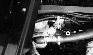
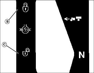
Using Fuel Shut-Off Valves
Turn the fuel shut-off valve(s) to the off (closed) position before transporting or storing the utility vehicle.
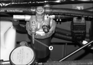
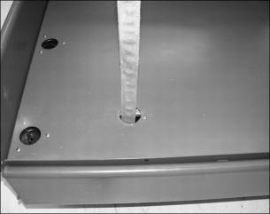
1. Raise cargo box to access fuel shut-off valve on fuel filter.
2. Turn lever (A) horizontal to "C" position to turn off fuel flow. Turn lever vertical to "O" position to turn on fuel flow.
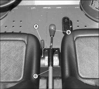
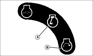
Using Park Brake
NOTE: Pushing down on brake pedal while locking and unlocking park brake decreases effort required to apply park brake lever.
Locking the Park Brake
2. Pull up on lever (A) and latch into position.
Unlocking the Park Brake
4. Release lever down completely.
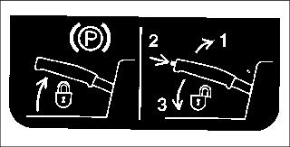
NOTE: Decal located on console below park brake lever.
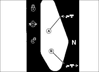
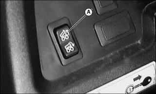
Operating Differential Lock
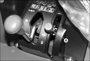
Differential lock (A) provides better traction when rear wheels start to slip. Engaging the differential lock will cause all rear wheels to turn together at equal speed.
Engaging the Differential Lock
1. Stop or reduce engine speed to 1\3 throttle or less.
2. Push differential lock lever forward to locked position (B):
· Differential lock will remain engaged as long as lever is forward.
· Panel indicator light will come on.
Disengaging the Differential Lock
NOTE: Panel light only indicates when lever is in ON or OFF position. To ensure true disengagement of differential lock, you must equalize torque on both axles.
1. Stop or reduce engine speed to 1\3 throttle or less.
2. Drive the vehicle straight ahead at a constant speed.
3. Pull lever rearward to unlocked position (C). Panel indicator light will go off.
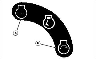
Using Transaxle Shift Lever
2. Allow engine to come to a low idle speed.
· Forward (A) - Push shift lever forward.
· Reverse (B) - Push shift lever to right, then pull rearward.
Starting the Engine
1. Sit on operator's seat. Do not start engine at this time.
2. Push down on accelerator pedal to check free movement of pedal assembly. Release pedal.
NOTE: The vehicle has a neutral start safety switch. The engine will not start unless the transaxle shift lever is in N (Neutral) position.
3. Move gearshift lever to N (Neutral) position.
5. Turn key switch to run position (A). Check the following indicator lights are on:
· Battery discharge indicator.
· Coolant temperature and engine preheat indicators for up to 8 seconds depending on air temperature.
6. Turn key to Start position (B) after coolant temperature and engine preheat indicators go out.
IMPORTANT: Avoid damage! Starter may be damaged if operated for more than 20 seconds at a time. Wait at least two minutes before trying again if engine does not start. |
7. Release key to the Run position when engine starts.
· If engine does not start within five seconds, turn key to off and wait ten seconds before trying to start again.
· In very cold conditions, attempt starting engine three times only, then wait 5 minutes before trying again. This will allow time for starter to cool and prevent damage to starter.
IMPORTANT: Avoid damage! Do not operate the engine at full throttle or under load until engine has warmed up, or engine damage could occur. |
8. Run engine at half speed for 2 or 3 minutes to warm the engine.
Stopping Engine
Always lock the park brake and remove the key before leaving the machine unattended. |
IMPORTANT: Avoid damage! If engine has been running hard and is hot, do not stop engine immediately. Remove load from engine. Run engine at 1/3 to 1/2 throttle for several minutes to cool engine. |
2. Move gearshift lever to N (Neutral) position.
4. Turn key switch to STOP position (A).
Operating the Vehicle
1. Move transaxle shift lever to forward or reverse gear position as desired.
2. Look in the direction the vehicle will travel.
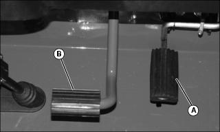
3. Push down accelerator pedal (A) slowly and smoothly to begin vehicle travel.
4. Release accelerator and apply brake pedal (B) evenly and firmly to slow down or stop.
Raising and Lowering Cargo Box Using Power Lift
1. Park the vehicle safely. (See Parking Safely in the SAFETY section.)
3. Raise cargo box by pressing and holding top of rocker switch (A). Release switch when box is at desired dump height or when reaching maximum height.
NOTE: Allowing the Power Lift actuator clutch to slip briefly (click or ratchet) after cargo box is fully lowered will help keep cargo box secure and reduce rattling caused by travel vibrations.
4. Completely lower cargo box by pressing and holding bottom of rocker switch.
NOTE: Hour meter will run whenever key is in RUN position. Turn key to Stop position after using the Power LIft option.
Dumping a Load
1. Back up vehicle to dump site.
2. Park the vehicle safely. (See Parking Safely in the SAFETY section.)
IMPORTANT: Avoid damage! Stop dumping immediately if actuator clutch slippage occurs. Lower cargo box completely and remove excess load by hand before dumping. |
4. Raise cargo box to dump load.
5. Lower cargo box when empty.
6. Latch tailgate closed. Do not drive vehicle with cargo box in raised position.
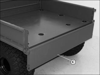
Operating the Tailgate
Lower Tailgate Using Tailgate Support
NOTE: Use the tailgate support to carry a longer load with tailgate down.
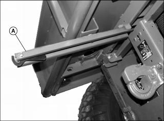
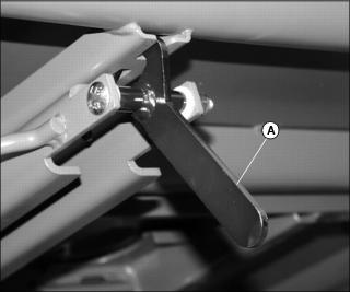
1. Pull tailgate support arm (A) out from under cargo box.

2. Pull latch rod handles (B) up and towards center of tailgate at the same time to release tailgate latches from holes (C) in side panel.
3. Lower tailgate (D) until resting on tailgate support arm. Latch hook/arm into tailgate.
4. Pull up tailgate to close and snap latch rods back into side panel holes at the same time.
5. Push tailgate support arm back under cargo box.
6. Push rod handles down to avoid snagging on clothing.
Lower Tailgate Without Tailgate Support
1. Pull latch rod handles (A) up and towards center of tailgate at the same time to release tailgate latches from holes (B) in side panel.
3. Pull up tailgate to close and snap latch rod handles back into holes at the same time.
4. Push rod handles down to avoid snagging on clothing.
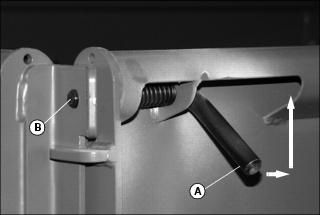
Latching the Tailgate to the Tailgate Support Arm
NOTE: The support arm has a latch handle (A) that will hold the lowered tailgate firmly to the support arm (B).
1. Pull the tailgate support arm out from under the cargo box.
2. Lower tailgate to support arm.
3. Pull up on the latch handle (A) until it connects into slot of support arm.
4. To release tailgate, push in on handle (A) and return support arm to the stored position under the cargo box.
5. Close cargo box and be sure the latch rods snap securely into the holes in the side panels.
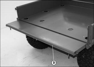
Lowering Cargo Box Side Panels
1. Lower the tailgate onto the tailgate support arm.

2. Lift latch (A) at the front of cargo box to disengage latch pin (B) and pull on the side panel (C) to lower.
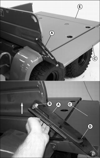
3. To raise side panel, lift latch (A) and raise panel (C) until the lower detent (D) in the latch engages latch pin (B).
4. Pull up tailgate (E) to close and snap latch rods back into holes at the same time.
5. Push rod handles down to avoid snagging on clothing.
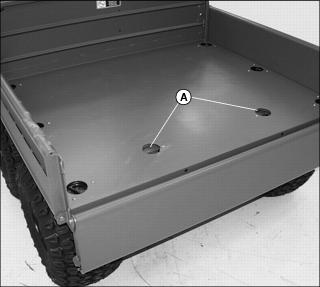
Using Cargo Box Tie-down Rings
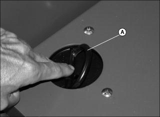
1. Place your finger on the flat of the tie-down ring and push to access the ring loop (A).
IMPORTANT: Avoid damage! To avoid damage to side panels and tailgate, place bulk of load over the main cargo box area (B). Do not overload tailgate or side panels. |
2. Arrange load so that the weight is centered over the main cargo area (B).
3. Secure loads to the tie-down rings in a safe and secure manner.
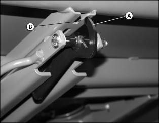
Using Sling Load Portal® Rings
NOTE: The Sling Load Portals (A) located to the rear of the cargo box allow access to the rear lift rings.
NOTE: There is a gap between the tab (B) and the frame stop (C). If necessary pry open the Sling Load Portal in the case of a tight condition.
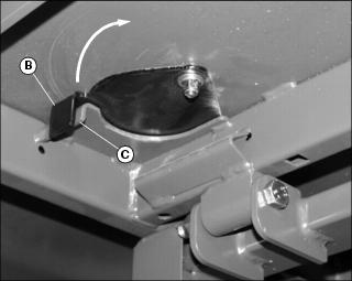
1. Reach under edge of cargo box to the tab (B) of the Sling Load Portal and swing open.
2. Place an approved lifting device through the Sling Load Portal in the cargo box.
NOTE: Rings on the four corners of the vehicle are for lifting or tiedown. Rings (D) must be free to rotate.
3. If not free to rotate, loosen nut until the rings (D) are free.
4. Secure the lifting device to the lifting ring (D).
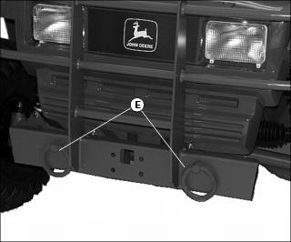
5. There are two lifting rings (E) on the front of the vehicle also.
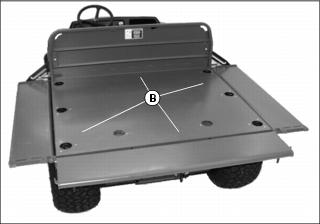
Loading the Cargo Box
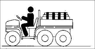
Maximum payload capacity on level terrain for the cargo box for the M-GATOR is 450 kg (1000 lb).
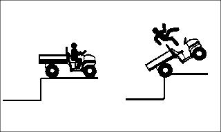
Reduce load and ground speed when operating over rough or hilly terrain. Do not overload vehicle. Limit loads to those that can be safely controlled.
Securely anchor and evenly distribute loads in cargo box, when loading objects into vehicle. Shifting loads will affect stability.
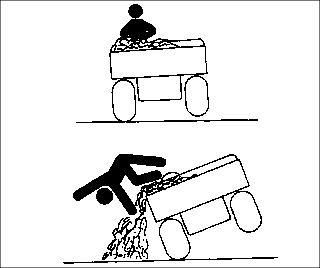
Avoid concentrated loads at rear or side of cargo box to prevent vehicle from tipping over. Be sure load is evenly distributed.
Because there is a big difference in weight between dry and wet sand, the only way of getting true weight of the load you are carrying is by using a weigh scale.
For example, dry sand weighing 450 kg (1000 lb) would be approximately 3/4 of cargo box volume for the M-GATOR.
Printed weight is normally on bagged and other material.
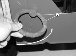
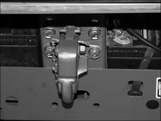
Using Pintle Hitch
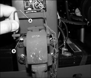
1. Remove wire lock (A) from lock pin (B) and remove lock pin.
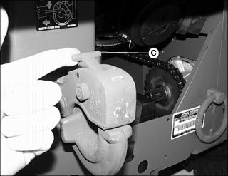
2. Pull the hitch lock (C) forward.
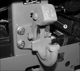
4. To lock hitch, install lock pin and wire lock.
Towing Loads
· Do not tow a load unless the cargo box is loaded.
· Do not tow a load that exceeds 636 kg (1400 lb).
· Do not exceed a tongue weight of 45 kg (100 lb).
· Never exceed 16 km/h (10 mph) when towing a load. Tow load at a speed slow enough to maintain control.
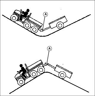
· Always use approved hitch and hitch point provided for the utility vehicle. DO NOT modify the hitch or hitch point in any way.
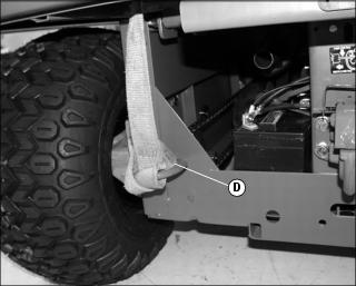
Transporting Vehicle
IMPORTANT: Avoid damage! Never tow the vehicle. Towing a vehicle will result in transaxle damage. Haul the vehicle on a heavy-duty trailer or on a full-size truck. |
NOTE: Space limitations may vary from one truck manufacturer to another. Short bed trucks do not have the necessary length requirement to accommodate the vehicle.

1. Drive utility vehicle onto the trailer or truck.
2. Leave transaxle shift lever in forward or reverse gear.
3. Park vehicle safely (See Parking Safely in the SAFETY section.)
4. Turn fuel shut-off valve, if equipped, to off position during transport.
5. Fasten vehicle to trailer or truck with straps, chains, or cables.
6. Equip the trailer or truck with all the necessary lights and signs required by local, state, provincial, or federal laws.