
Assembly
Remove Tractor from Crate
Return steel envirocrate. Call 1-800-JDLAWNS for procedure if needed.
Remove Hood
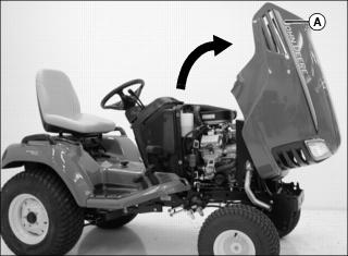
1. Lift rear of hood (A) and tilt to fully upright position.
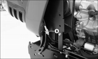
2. Disconnect headlight harness (B) on left side of machine.
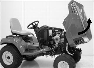
3. Pull hood forward and roll hood up and out of rail.
Charge and Connect Battery
Check Battery
Battery is filled with acid and charged when it left the factory. To extend battery life, charge battery prior to delivery.
Check battery voltage. Battery should be charged for 30 minutes at 5-10 amps if voltage is below 12.3 volts. Battery is fully charged at 12.6 volts.
Connect Battery
1. Use a wire brush to remove any glazing from battery posts and cable ends.
2. Connect red positive (+) cable to battery. Apply general purpose grease or silicone spray to terminal to help prevent corrosion. Make sure connection is tight. Push cover over positive terminal.
3. Connect black negative (-) cable to battery. Apply general purpose grease or silicone spray to terminal to help prevent corrosion. Make sure connection is tight.
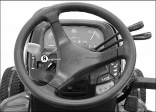
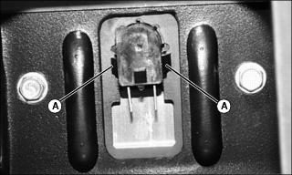
Install Steering Wheel
1. Install steering wheel on shaft.
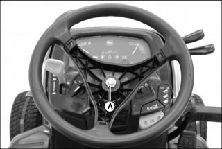
2. Install and tighten nut (A) to 38 N·m (28 lb-ft).
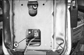
Install Seat (Standard Models)
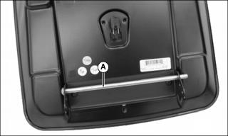
1. Remove rod (A) from seat pan bracket.
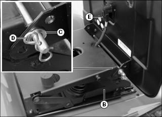
2. Install seat on suspension (B).
3. Install rod through suspension and middle hole in seat pan bracket.
4. Install washer (C) and cotter pin (D) on rod.
5. Connect seat switch harness (E).
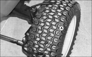
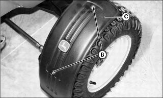
Check Tire Pressure
2. Check tire pressure with an accurate gauge.
3. Add or remove air, if necessary.
Special Edition Assembly
NOTE: Follow other tactor assembly instructions in this section before completing these instructions. Then check machine safety systems.
Install Fenders
1. Locate wire brackets (A) for front fenders on each side of machine.
2. Install bolt (B) into washer, fender (C) and wire bracket. Install nut.
Install Shield
NOTE: Shield is only for use on 62C mower deck. Do not use with other mower decks.
1. Cut shield on both ends of slot (A) for two parts.
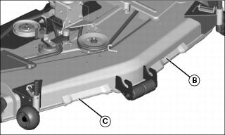
2. Install shield part (B) and part (C) over the front lip of the deck as shown.
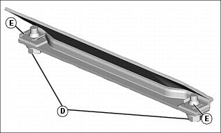
3. Install M8x20 bolts (D) through the mower deck lip and shield and into the clip nuts (E) on the shield parts.
Install Seat
1. Turn seat over to see opening for seat switch.
2. Squeeze tabs (A) together and slide into slot and release tabs.
3. Connect the seat switch harness (B) to the seat switch.
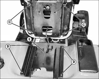
4. Align holes (C) in seat assembly with holes (D) in seat base.
5. Insert seat switch harness into notch (E).
6. Install the four self-tapping bolts up through holes in seat base into holes in seat assembly. Tighten bolts.
Pre-Delivery
Check and perform the following on all tractors.
1. Lubricate all grease fittings. Refer to Operator's Manual as needed for location information.
2. Check all fluid levels. Refer to Operator's Manual or under hood decal as needed for oil type and specifications:
· Engine coolant - check level in radiator and in overflow reservoir.
· MFWD axle oil (if equipped).
· Mower deck or attachment gearbox oil (if equipped).
· Fill fuel tank with fresh stabilized fuel to prevent gum and varnish from forming in fuel system. Use John Deere TY15977 Fuel Stabilizer.
3. Check freewheel valve - tractor should be able to be pushed forward and backward with lever engaged and brake off.
4. Check cruise control latch function:
· Depress forward pedal, engage cruise by lifting lever up. Forward pedal should stay down.
· Tap park brake pedal or forward pedal. Cruise control should disengage.
5. Check hydraulic functions - raise and lower mower deck. Cycle several times to remove any trapped air.
6. Check operation of instrument panel indicator lights, headlights, taillights, backup lights and rear work lights. See Operator's Manual for information on instrument panel light functions.
7. Wash tractor to remove dirt and dust. Wax hood and fender deck for scratch protection.
Testing Safety Systems
The safety systems installed on your machine should be checked before each machine use. Be sure you have read the machine operator manual and are completely familiar with the operation of the machine before performing these safety system checks.
Use the following checkout procedures to check for normal operation of machine.
If there is a malfunction during one of these procedures, do not operate machine. See your authorized dealer for service.
Perform these tests in a clear open area. Keep bystanders away.
Testing PTO/RIO Switch
Test 1:
1. Depress brake pedal, or lock park brake.
2. Pull PTO/RIO switch up to engage PTO.
Test 2:
2. Unlock park brake and release brake pedal.
3. Move throttle lever up to maximum engine speed.
4. Pull PTO/RIO switch up to engage PTO.
Testing Seat Switch
Test 1:
2. Move throttle lever up to maximum engine speed.
3. Unlock park brake and release brake pedal.
4. Pull PTO/RIO switch up to engage PTO.
5. Raise up off seat. Do not get off machine.
Test 2:
3. Unlock park brake and release brake pedal.
4. Raise up off seat. Do not get off machine.
Testing Park Brake Switch
Test 1:
1. Park machine safely. (See Parking Safely in the SAFETY Section.)
2. Unlock park brake and release brake pedal.
Test 2:
4. Raise up off seat. Do not get off machine.
Testing Reverse Implement Option (RIO)
Before backing up, carefully check the area around the machine. |
1. Park machine safely. (See Parking Safely in the SAFETY Section.)
3. Move throttle lever up to maximum engine speed.
4. Engage PTO to start attachment.