
Service
Service Intervals
Servicing Your Machine
Please use the following timetables to perform routine maintenance on your machine.
Before Each Use
• Lubricate caster wheel bearings.
• Lubricate caster wheel spindles.
• Check chain tension. Adjust if necessary.
Every 25 Hours
• Check wear on plastic chain guide. Replace if necessary.
As Needed
• Replace PTO shaft shear bolt.
• Replace brush shaft shear bolts.
Grease
The following greases are preferred:
• John Deere Multi-Purpose SD Polyurea Grease
• John Deere Multi-Purpose HD Lithium Complex Grease
If not using any of the preferred greases, be sure to use a general all-purpose grease with an NLGI grade No.2 rating.
Wet or high speed conditions may require use of a special-use grease. Contact your Servicing dealer for information.
Lubrication
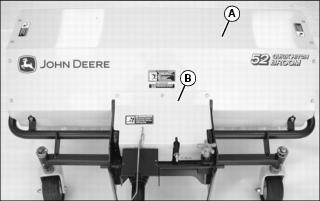
Lubricating Broom
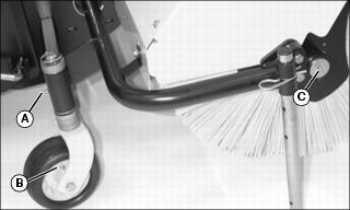
Lubricate grease fittings on both sides of broom with recommended grease:
• Wheel spindles (A) on broom and optional thatching kit if installed.
• Wheel bearings (B) on broom and optional thatching kit if installed.
Lubricating PTO Shaft
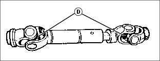
Lubricate each PTO shaft U-joint (D) with recommended grease.
Gear Case Oil
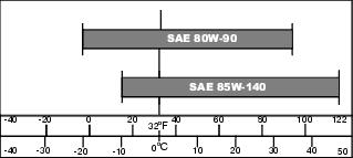
Use oil viscosity based on the expected air temperature range during the period between oil changes
The following John Deere gear case oil is preferred:
• GL-5 GEAR LUBRICANT® (SAE 80W-90)
The following John Deere gear case oil is also recommended if preferred oil is not available:
• GL-5 GEAR LUBRICANT® (SAE 85W-140)
Other gear case oils may be used if recommended John Deere gear case oils are not available, provided they meet the following specification:
• API Service Classification GL–5.
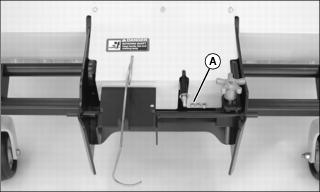
Checking Gearbox Oil Level
NOTE: Check gearbox oil level when oil is cold. Changing the gearbox oil is not required.
1. Park machine safely. (See Parking Safely in the SAFETY section.)
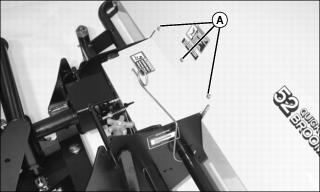
2. Remove three bolts (A) and gearbox shield.
IMPORTANT: Avoid damage! Prevent dirt and other contaminants from entering the gearbox. Clean area around gearbox check plug before removing. |
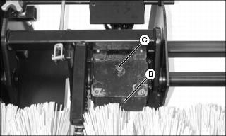
3. Clean area around plug (B). Remove plug.
4. Oil level should be level with plug hole.
5. Clean area and remove plug (C) to add recommended oil if needed.
Replacing PTO Shaft Shear Bolts
1. Park machine safely. (See Parking Safely in the SAFETY section.)
2. Remove any remaining parts of broken or damaged shear bolt.
IMPORTANT: Avoid damage! Broom uses two different shear bolt lengths and diameters. Use of wrong shear bolt can damage the gearbox. |
3. Remove one 5.7 cm (2.25 in.) shear bolt (A) and locknut stored at back side of broom.
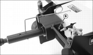
4. Align hole in PTO shaft with hole in stubshaft.
5. Install shear bolt (B) and locknut.
Replacing Brush Shaft Shear Bolts
1. Park machine safely. (See Parking Safely in the SAFETY section.)
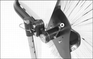
2. Remove any remaining parts of broken or damaged shear bolt (A) on brush shaft ends.
3. Install new shear bolt and locknut.
Replacing Brush Sections
Remove Old Brush Sections
1. Park machine safely. (See Parking Safely in the SAFETY section.)
2. Remove all bolts in main shield (A). Remove main shield with gearbox shield (B).
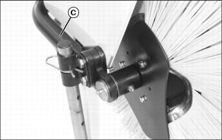
3. Block broom or support broom with a suitable lifting device at area just behind parking stands (C).

Picture Note: Brush sections removed from core.
4. Remove bolts and locknuts (D) in chain guard. Remove chain guard.
5. Remove nut (E), washer (F) and spring (G) from idler tension bolt.

6. Locate master link retaining clip (H) on drive chain. Remove and retain the clip.
7. Remove master link to disconnect chain. Retain master link and remove the chain.
Picture Note: Brush sections removed from core.
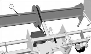
8. Support core (I) near both ends with a suitable lifting device
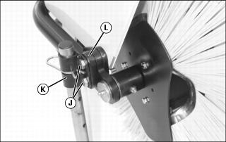
9. Remove two bolts (J) and nuts attaching parking stand to broom. Remove brackets (K) and spacer (L) on both sides of broom. Remove core with brush sections from broom.
Picture Note: Brush sections shown installed on core on broom.
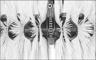
10. Twelve brush sections are installed on both sides of the core. Note the brush section installation sequence for each side:
a. Slide the first brush section onto the core against the inside retainer plate (M) as shown.
b. Slide eleven additional brush sections onto the core in an alternating pattern.
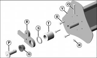
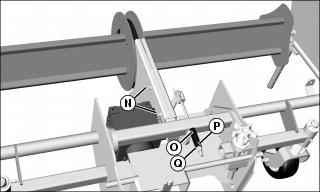
11. Remove locknut (N) and shear bolt (O). Remove core pin (P), flange bearing (Q), core retainer (R), thrust bearing (S), tube (T) and three screws (U). Remove retainer plate (V).
12. Remove brush sections from core.
Install New Brush Sections
1. Replace bush sections as needed in correct installation sequence.

2. Install retainer plate (A) on core with three screws (B).
3. Install tube (C), thrust bearing (D), core retainer (E), flange bearing (F), core pin (G), shear bolt (H) and locknut (I).

4. Install broom core, spacers (J) and parking stand brackets (K) with two bolts (L) and nuts.
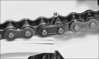
5. Install and connect drive chain with master link and retaining clip (M).
Picture Note: Brush sections removed from core.
6. Install chain guard with bolts and locknuts (N).
7. Install spring (O), washer (P) and nut (Q) on idler tension bolt.
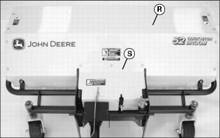
8. Install main shield (R) with gearbox shield (S).
Adjusting Chain Tension
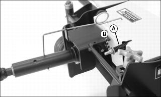
• Early Models: Measure the length of the compression spring (A) on the idler tension bolt. The spring length must be between 40 - 50 mm (1.6 - 2.0 in.) to maintain proper tension. Loosen or tighten the nut (B) as needed.
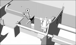
• Later Models: Compression spring should be at end of indicator (A) to maintain proper tension. Loosen or tighten the nut (B) as needed