
Installing
Preparing the Vehicle
Required Equipment
Machine must be equipped with the following options to attach and operate the broom:
Machine Setup
NOTE: It is recommended to install 4-ply tires on your machine for heavy duty sweeping operation. See your machine operator’s manual.
2. Check tractor tire pressures.
3. Close the SCV lockout valve before installing broom.
Installing Ballast
When the attachment is removed, also remove any ballast that was added to the machine. Use only attachments and accessories recommended by the manufacturer. |
NOTE: Ballast weights are not required for use with the broom but may improve traction in some operating conditions.
If added traction is required while operating broom:
• Install chains on drive tires.
• Install wheel weights on drive wheels or use liquid ballast in drive tires.
Closing SCV Lockout Valve
2. Turn the lift adjustment stop dial on mower to highest position.
3. Start the engine. Raise mower lift arms completely using the upper hydraulic control lever.
4. Park machine safely (See Parking Safely in SAFETY).
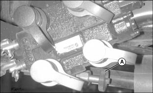
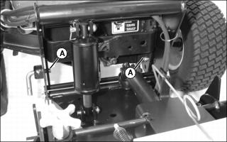
5. Turn SCV lockout valve (A) clockwise completely to close the valve. This prevents hydraulic flow to mower and rear implement lift and directs full pressure to the broom hydraulic circuits for best performance.
Attaching Broom to Front Quick Hitch
1. Park machine safely. (See Parking Safely in SAFETY section.)
2. Review instructions on using hydraulic control levers included in your tractor operator’s manual.
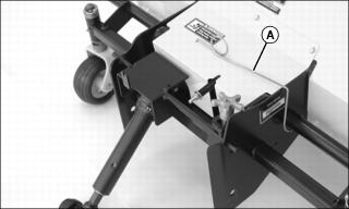
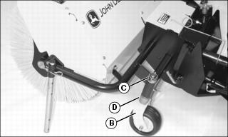
3. Remove the PTO shaft support (A) from storage position.
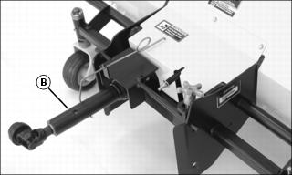
4. Swing shaft support toward center of broom frame and position as shown. Place the PTO shaft (B) in the support.
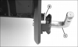
5. Rotate both L-pins (C) on the tractor front quick hitch, and turn to unlocked position with roll pin (D) in grooves as shown.
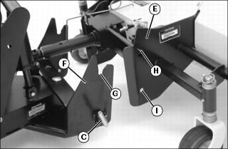
7. Drive tractor forward and align broom mounting frame (E) with front quick hitch (F). Notches (G) in hitch must be lower than pins (H) on broom frame.
• Push the lower hydraulic control lever on the tractor forward to lower the hitch. Pull the lower hydraulic control lever rearward to raise the hitch.
• Push the upper hydraulic control lever on the tractor forward to angle the hitch to the left. Pull the upper hydraulic control rearward to angle the hitch to the right.
8. Drive tractor forward slowly to engage pins (H) in notches (G).
9. Raise the hitch, checking to be sure pins engage notches. Lower the hitch until L-pins (C) snap into holes (I) on sides of broom frame.
10. Park machine safely (See Parking Safely in SAFETY).
11. Check to be sure L-pins are in locked position, fully engaged in broom frame. Adjust as needed.
Checking and Adjusting L-Pin Engagement
IMPORTANT: Avoid damage! Broom could slide out of position on quick hitch if L-pins are not properly engaged. Check engagement of L-pins before operating and adjust as needed. |
Checking L-Pin Engagement
1. Make sure both L-pins (A) pass completely through holes in broom mounting frame.
2. Push broom as far as possible to the right and left. Make sure L-pins remain in the mounting frame holes.
3. Reverse the installation if the L-pins disengage or do not pass completely through holes in mounting frame.
Reversing the L-Pins
1. Remove broom from front quick hitch.
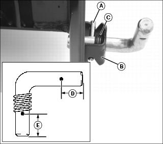
2. Remove roll pin (A) using a punch. Retain the roll pin.
3. Pull L-pin from bracket (B) and remove spring (C).
NOTE: The L-pin legs are different lengths. Leg (D) is 23 mm (0.9 in.) and leg (E) is 27 mm (1.1 in.).
4. Hold spring inside bracket. Reverse the L-pin and insert longer leg (E) through bracket and spring.
7. Install broom on front quick hitch.
8. Push broom as far as possible to the right and left. Make sure L-pins remain in the mounting frame holes.
Connecting PTO Shaft
Stop the engine and be sure the PTO shaft is stopped before getting near it. |
IMPORTANT: Avoid damage! Failure to lock the PTO shaft support into the storage position will cause damage to the PTO shaft and support. |
1. Lift the PTO shaft from the PTO shaft support (A).

2. Put PTO shaft support in storage position as shown.
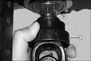
3. Pull back collar (C) on PTO shaft coupler.
4. Align coupler splines with splines on PTO output shaft (D). Slide coupler onto PTO output shaft until collar snaps back to the locked position.
5. Move PTO shaft forward and rearward to ensure it is locked in place.
Raising Parking Stands
Install broom parking stands in the raised position.
Leveling the Broom
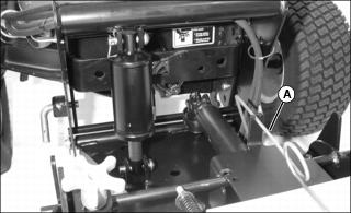
2. Park machine safely on level surface with installed broom in float position. (See Parking Safely in SAFETY section.)

Picture Note: Broom removed from tractor. Broom must be installed to check level.
3. The swing plate (A) on the front quick hitch should be horizontal or parallel to ground with installed broom in float position.
• If broom is level, you should not need to check again unless the broom is installed on a different tractor model.
• If broom is not level, determine how far you need to raise or lower the broom wheels to level the broom, and adjust the broom wheel height.
Adjust Wheel Height
1. Park machine safely with broom raised. (See Parking Safely in SAFETY.)
NOTE: Each spacer provides 13 mm (1/2 in.) of broom height adjustment.
• Move spacers to top of spindle to lower brush head.