
Service Mower
Removing Mower
1. Park machine safely. (See Parking Safely in the Safety section.)
2. Allow engine and muffler to cool completely.
3. Adjust mower cutting height to lowest position.
4. Move mower engagement lever to stop position.
5. Put wood blocks under each side of mower deck.
NOTE: If you have a lift assist installed on your machine (standard with 48C deck, optional with other decks), you may need to lower deck and then pull lift pedal back by hand to lock the lift lock lever.
6. Lower mower deck onto blocks, pull back lift pedal, and slide lift lock lever up to lock draft arms down.
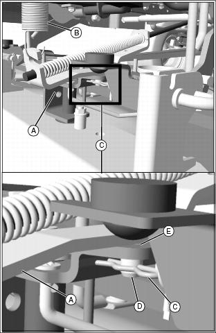
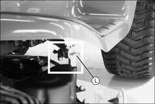
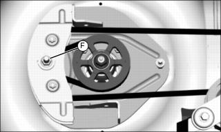
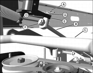
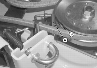
Picture Note: View from beneath right side of tractor.
7. Hold PTO rod bracket (A) near spring (B) and remove spring locking pin (C) from drilled pin (D) beneath PTO rod bracket. Allow spring to slowly pull PTO rod up from bracket (E) on mower deck and toward machine.
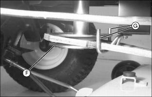
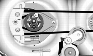
8. Remove belt from engine drive sheave (F) and belt guides (G).
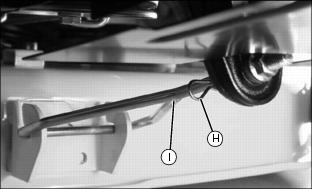
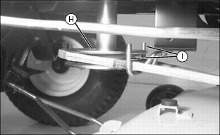
9. Remove spring locking pin (H) from front draft rod (I).
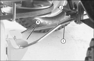
10. Remove front draft rod (I) from hole in tractor bracket (J) and from mower brackets (K).
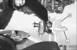
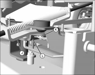
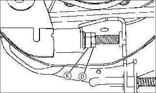
Picture Note: Close-up of draft arm and J-pin
11. Pull and rotate J-pin (L) to release and move draft arm (M) away from deck bracket (N). Repeat on other side.
Hold lift pedal securely when releasing from lock (lower) position. |
12. Raise draft arms to transport position:
a. Pull and hold lift pedal by hand.
c. Push down and hold lift pedal.
d. Pull up lift lock lever to lock draft arms in transport position.
13. Remove wood blocks from both sides and slide mower out from under tractor.
Installing Mower
1. Park machine safely. (See Parking Safely in the Safety section.)
2. Allow engine and muffler to cool completely.
3. Adjust mower cutting height to lowest position.
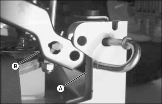
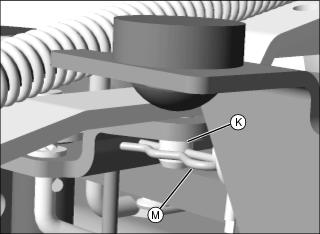
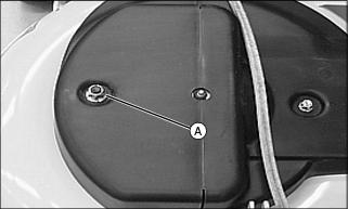
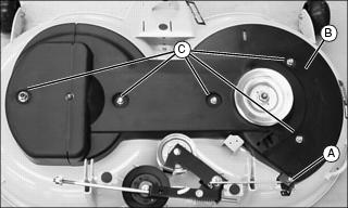
Picture Note: J-pin pulled back to show hole alignment for draft arm and deck bracket
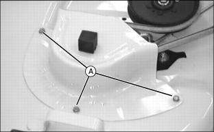
4. Slide mower deck, guide wheels in front, under tractor and line up deck bracket (A) with draft arm (B).
5. Put wood blocks under each side of mower deck.
7. Pull lift pedal by hand to lower draft arms. Hold pedal securely and lock lift lock lever.
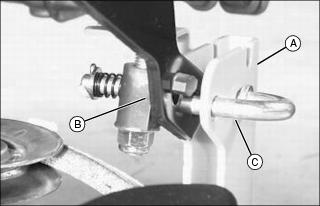
8. Pull back J-pin (C) and insert through deck bracket (A) and draft arm (B). Make sure pin installs completely through deck bracket.

9. Install front draft rod (D) into mower bracket (E) and then into hole in tractor bracket (F). Make sure nut and rounded bushing are on front side of tractor bracket.

10. Install spring locking pin (G) with loop of pin hanging down.
IMPORTANT: Avoid damage! The belt will be damaged if installed wrong. Route the belt properly through belt guides. See belt routing label on mower deck. |
11. Put mower drive belt on engine drive sheave (H) and route through both belt guide loops (I). Make sure belt is on all sheaves and idlers and is inside all belt guides, front and rear.
12. Remove wood blocks from both sides of mower.
IMPORTANT: Avoid damage! If the mower engagement rod is not adjusted properly, the mower belt may slip or drag on blade sheave resulting in belt damage. |
· Mower is at lowest possible cutting height.
· Mower is at mowing position.
· Mower engagement lever is pulled back into stop position.
· Gauge wheels are not touching the ground.
Picture Note: View from beneath right side of tractor.
Picture Note: Close-up of spring locking pin (M).
13. Pull down PTO rod bracket (J) and insert drilled pin (K) into bracket (L) on mower deck.
14. Insert spring locking pin (M) into drilled pin (K).
Replacing Mower Drive Belt (38-Inch and 42C Decks)
NOTE: In this procedure the mower deck is removed for easier access.
1. Park machine safely. (See Parking Safely in Safety section.)
2. Allow engine and muffler to cool completely.
4. Remove three cap screws (A) or lock nuts (on 42C) and belt shield.
5. On 42C deck, remove wear plate beneath shield.
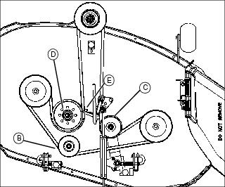
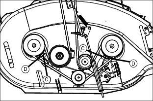
6. Loosen rear idler (B) and tensioning sheave (C). On 42C deck, also loosen fixed idler (D).
9. Install new belt on mower as shown above.
10. Tighten rear idler and tensioning sheave.
11. On 42C deck, install wear plate and tighten fixed idler.
IMPORTANT: Avoid damage! Make sure locator on belt guide (E) is aligned with hole on fixed idler (D) mounting bracket before tightening. |
12. Install belt shield and fasten with three cap screws or lock nuts (on 42C).
13. Install mower deck and adjust mower engagement rod, if necessary.
Replacing Mower Drive Belt (48C Deck)
1. Park machine safely. (See Parking Safely in Safety section.)
2. Allow engine and muffler to cool completely.

4. Remove flange nuts (A) and left and right belt shields.

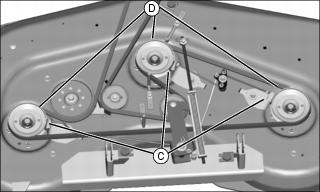
5. Loosen idlers (B) and belt guides (C).
8. Install new belt on mower as shown above.
9. Align belt guide locators with holes in deck and tighten belt guides (C).
10. Align notch in belt guide on fixed idler with locator on idler bracket and tighten idlers (B).
11. Install belt shields and fasten with flange nuts.
12. Install mower deck and adjust mower engagement rod, if necessary.
Replacing Mower Drive Belt (Freedom 42 Deck)
1. Park machine safely. (See Parking Safely in Safety section.)
2. Allow engine and muffler to cool completely.

4. Remove self-tapping cap screws (A).
5. Move brake assembly (B) away from sheave (C) and drive belt.
6. Loosen idler (D) and tensioning idler (E) just enough to slip belt past the guides.
7. Remove drive belt and clean top of mower.
8. Install new belt on mower deck as shown.
9. Tighten idler (D) and tensioning idler (E).
10. Align brake assembly (B) with right spindle sheave (C) and fasten with self-tapping cap screws (A). Brake pad must seat against top of sheave.
11. Install mower and adjust mower engagement rod, if necessary.
Adjusting Mower Timing Belt Tension (Freedom42 Deck)
2. Move lift lever to mowing position and move to left side of mower.
NOTE: Mower timing belt cover can be unfastened and flipped open on the left side, exposing the tension adjustment mechanism, without having to remove the mower or the timing belt cover.
Picture Note: Mower removed for photo clarity
3. Remove flange lock nut (A) to flip open left spindle cover.
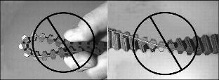
4. Check timing belt for damage. If the belt is damaged, replace the timing belt. If not damaged, complete remaining steps to adjust belt.

5. Remove top washer first, then loosen idler assembly center nut (B) one full turn only.
6. Check that blades are timed properly (90° from each other). If blades are out of time, set blades to proper timing.
7. Turn left spindle sprocket (C) to be sure belt is seated properly in the sprockets and idlers.
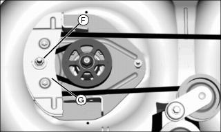
IMPORTANT: Avoid damage! Incorrect belt tensioning can cause belt damage. Do not over tighten belt tensioning spring assembly. |
8. Loosen jam nut (D) and adjusting nut (E) so that there is a small air gap between washer (F) and mating surface of spring bushing (G).
9. Rotate adjusting nut (E) clockwise until washer (F) makes solid contact with the mating surface of spring bushing (G).
10. Tighten idler assembly center nut (B) to 87 N·m (64 lb-ft).
11. Tighten jam nut (D) against adjusting nut (E) to 27 N·m (20 lb-ft).
12. Turn left spindle sprocket (C) to be sure belt is seated properly in the sprockets and idlers.
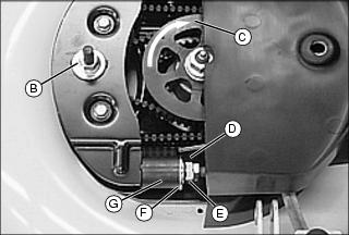
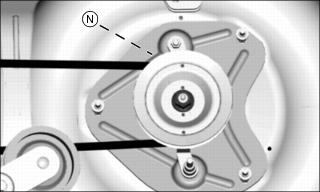
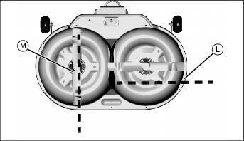
NOTE: The position of the drain holes in the spindle sheave (A) and the indentations in the timing sprocket (M) are in alignment with the mower blades (K) and (L).
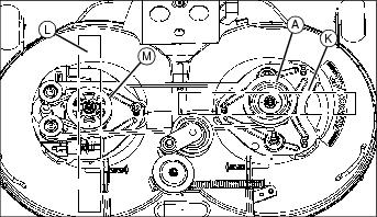
13. Check that blades are timed properly (90° from each other). If blades are out of time, set blades to proper timing.
14. Install top washer on top of center nut (B) and close left spindle cover.
15. Fasten cover with flange lock nut and tighten to 14 N·m (10 lb-ft).
Replacing Mower Timing Belt And Adjusting Blade Timing (Freedom42 Deck)
IMPORTANT: Avoid damage! Damage may occur to the belt or blades after a major blade impact: |
1. Park machine safely. (See Parking Safely in Safety section.)
2. Allow engine and muffler to cool completely.
5. Carefully hold blade with glove, use a hand torque wrench, and tighten bolt to 57 N·m (42 lb-ft).
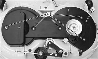
6. Move spindle brake assembly (A) back to clear timing belt cover (B).
7. Remove five flange lock nuts (C) and cover (B).
8. Turn jam nut (D) and adjusting nut (E) counterclockwise to end of threaded rod, and remove tensioning spring assembly.
9. Remove washer and center nut (F) and move fixed idler assembly (G) close to the spindle sprocket. Do not loosen other idler assembly hardware.
10. Raise idler assembly upward as you carefully remove timing belt from the left spindle sprocket.

11. Remove spacer (H) located between fixed idler assembly plates and carefully pull belt from assembly.
12. Loosen two belt guides (I) and rotate away from left sprocket.
13. Remove timing belt, replace if necessary.
IMPORTANT: Avoid damage! Mower blades can collide if not properly timed. Blades must be aligned perpendicular (90° ) to each other. |
NOTE: The position of the drain holes in the spindle sheave (J) and the indentations in the timing sprocket (K) are in alignment with the mower blades (L) and (M).

14. Position mower blades (L) and (M) 90° from each other.
15. Install new mower deck timing belt:
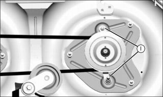
a. Route belt around right spindle sprocket (N) located under the mower drive belt sheave.
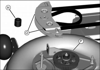
b. Route belt around outside of idlers and then in between the fixed idlers (O), pulling a belt loop through the idler assembly.
c. Insert spacer (H) between fixed idler plates and idlers.
d. Install the fixed idler assembly on the stud of the left support plate as you wrap belt loop around left spindle sprocket (P).
16. Install washer and center nut (F) on fixed idler assembly. Leave nut loose at this time.
Picture Note: Underside of deck shown for illustration only
17. Check that blades (L) and (M) are 90° from each other.
IMPORTANT: Avoid damage! Incorrect belt tensioning can cause belt damage. Do not over tighten belt tensioning spring assembly. |
18. Install tensioning spring assembly and adjust timing belt tension:
a. Align notch (Q) in idler assembly with tab on spring bushing (R).
b. Rotate adjusting nut (E) clockwise until the washer (S) makes solid contact with the surface of the spring bushing (R).
c. Turn adjusting nut an additional 1/2 turn to allow for new belt stretch. Do not over tighten.
d. Rotate right spindle sheave clockwise and observe that belt is riding properly in sprockets and idlers.
e. Tighten jam nut (D) against adjusting nut.
19. Tighten center nut (F) to 73 N·m (54 lb-ft).
20. Install top washer on top of center nut.
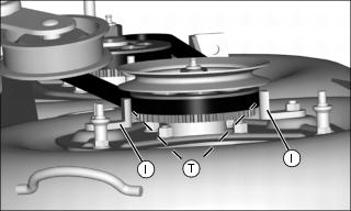
IMPORTANT: Avoid damage! Check belt guide-to-sprocket rim clearance. Measuring clearance incorrectly can cause belt or blade damage. |
a. Hold a 1 mm (0.039 in.) shim/gage between belt guides and sprocket rim, location (T), and rotate belt guides (I) clockwise against gage.
b. Tighten belt guide nuts to 24 N·m (18 lb-ft).
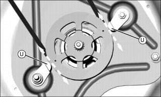
Picture Note: Right spindle sheave removed for photo clarity
c. Remove gage. Clearance (U), one on each side, should be 1contact belt guide.
22. Install timing belt cover (B) and fasten with five nuts (C). Tighten nuts to 14 N·m (10 lb-ft).
24. Install mower and adjust mower engagement rod, if necessary.
Adjusting Mower (PTO) Engagement Rod
IMPORTANT: Avoid damage! If the mower engagement rod is not adjusted properly, the mower belt may slip or drag on blade sheave resulting in belt damage. |
· Mower is at lowest possible cutting height.
· Mower is at mowing position.
· Mower engagement lever is pulled back into stop position.
· Gauge wheels are not touching the ground.
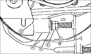
Picture Note: View from beneath left side of tractor looking across mower deck, up and toward rear
1. Pull pin (A) to disconnect PTO rod.
2. Move PTO engagement rod (B) over brakeshaft (C). Pull PTO engagement rod forward until idler arm can no longer rotate. Align adjustment pin (D) with hole in tractor arm (E).
3. If pin (D) does not line up, loosen lock nut (F) and turn pin until pin slips freely into hole. Tighten lock nut.
4. Insert adjustment pin into hole in tractor arm.
5. Install washer (G) and spring locking pin (A) to fasten adjustment pin to arm.
Adjusting Spindle Brakes
NOTE: This procedure applies only to the 38-Inch, 42C and 48C mowers.
The Freedom42 mower has a self-adjusting spindle brake assembly - no adjustment is necessary.
1. Park machine safely. (See Parking Safely in the Safety section.)
2. Adjust mower cutting height to lowest position.
4. Remove gauge wheels if they contact the ground.
5. Push mower engagement lever forward.
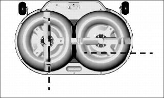
Picture Note: 38-Inch deck used for illustration
7. Measure distance between brake pad surface (A) and pulley braking surface (B). Brake to pulley distance should be 2 - 3 mm (0.08 - 0.12 in.) at all spindles.
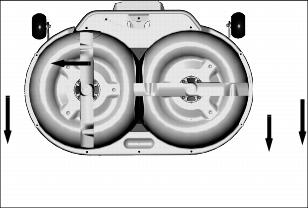
Picture Note: 38-Inch and 42C have two spindles
Picture Note: 48C has three spindles
· Turn adjusting nuts (C) on end of brake rods in correct direction to set brakes at proper distance from pulleys. Adjust at all spindles (D).
9. Install gauge wheels if removed.
Checking for Bent Mower Blades
1. Park machine safely. (See Parking Safely in the SAFETY section.)
2. Raise mower to highest position to access blades.
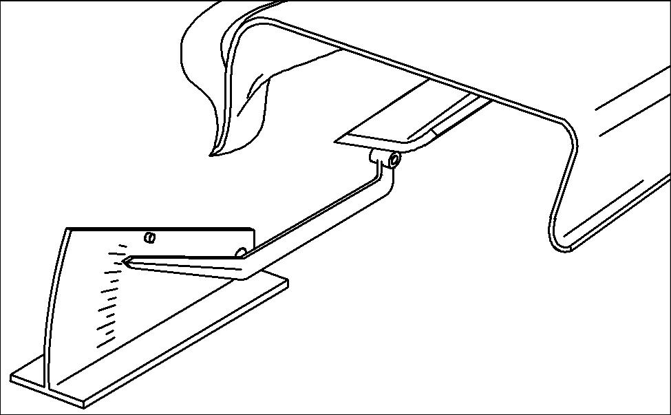
Picture Note: Mower deck with side discharge used for illustration
3. Measure distance (A) between blade tip and flat ground surface.
4. Rotate blade 180° and measure distance between other blade tip and flat ground surface.
5. Install new blade if the difference between the two measurements is more than 3 mm (1/8 in.).
Servicing Mower Blades (38-Inch, 42C and 48C Decks)
Removing Mower Blades
1. Park machine safely. (See Parking Safely in the Safety section.)
2. Raise mower deck to gain access to mower blades. If necessary, remove mower deck after allowing engine and muffler to cool completely.
3. Block mower blade with a piece of wood to prevent it from rotating.
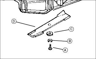
4. Loosen and remove cap screw (A), hardened washer (B), blade washer (C) and blade (D). (Note: No hardened washer on 48C.)
5. Inspect blades; sharpen, balance or replace blades as necessary.
Installing Mower Blades
NOTE: Do not lubricate cap screw.
1. Check that deflector cup (A) is properly seated between mower spindle and blade (B).
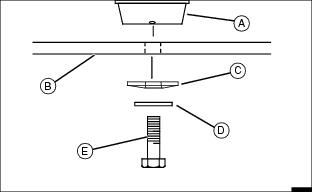
2. Position mower blade (B) with the cutting edge towards the ground onto the mower spindle.
3. Install blade washer (C) with cup side toward the blade.
4. Install hardened washer (D). (Note: No hardened washer on 48C.)
5. Install and hand tighten cap screw (E) until mower blade is in full contact with spindle.
6. Block mower blade with a piece of wood to prevent rotating and tighten cap screw to specifications:
Servicing Mower Blades (Freedom42 Deck)
Removing Mower Blades
1. Park machine safely. (See Parking Safely in the Safety section.)
2. Raise mower deck to gain access to mower blades. If necessary, remove mower deck.
3. Block mower blade with a piece of wood to prevent rotating.

4. Loosen and remove bolt with washer (A), and blade (B).
5. Inspect blades; sharpen, balance or replace blades as necessary.
Installing Mower Blades
1. Check mower to be sure you are installing the blades on the correct side. Right and left sides are marked on rear draft brackets of mower deck.
· There are direction arrows located on each outside edge of the mower. There is a right and a left side blade. The blades are marked for identification.
2. Check that deflector cup (A) is properly seated between mower spindle and blade.
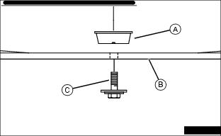
3. Position mower blades (B), with the cutting edge towards the ground, onto the mower spindle and align key on bottom of spindle with slot in blade.
4. Install and hand tighten bolt with washer (C) until mower blade is in full contact with spindle.
5. Block mower blade with a piece of wood to prevent rotating and tighten bolts to 57 N·m (42 lb-ft).
6. Check mower deck timing and adjust if necessary.
Sharpening Blades
· Sharpen blades with grinder, hand file, or electric blade sharpener.
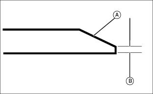
· Keep original bevel (A) when grinding.
· Blade should have 0.40 mm (1/64 in.) cutting edge (B) or less.
· Balance blades before installing.
Balancing Blades
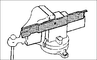
2. Put blade on nail in a vise. Turn blade to horizontal position.
3. Check balance. If blade is not balanced, heavy end of blade will drop.