
Assembly
Bag of Parts
Charge and Connect Battery

1. Remove and discard the red (+) positive, and black negative (-) protective caps from the battery terminals.
3. Clean both battery terminals and battery cable ends with a wire brush until bright.
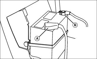
4. Connect red positive (+) cable (A) to battery. Apply petroleum jelly or silicone spray to terminal to prevent corrosion. Make sure connection is tight. Install the red terminal cover.
5. Connect black negative (-) cable (B) to battery. Apply petroleum jelly or silicone spray to terminal to prevent corrosion. Make sure connection is tight.
Check Engine Oil Level
NOTE: Check oil twice a day if you run engine over 4 hours in a day.
1. Park machine safely. (See Parking Safely in the Safety section.)
3. Clean area around dipstick to prevent debris from falling into crankcase.
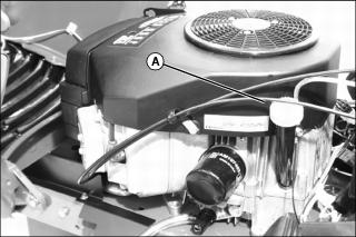
4. Remove dipstick (A). Wipe with clean cloth.
5. Install dipstick in tube, but do not tighten. Let dipstick threads rest on top of tube, and turn cap counterclockwise until it starts to engage threads.
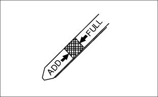
7. Check oil level on dipstick. Oil must be between ADD and FULL marks.
8. If oil level is low, add oil to bring oil level no higher than FULL mark on dipstick.
9. Install and tighten dipstick. Lower hood.
Install Steering Wheel
1. Put John Deere Multi-Purpose lubricant or an equivalent on the steering shaft.
2. Install steering wheel with John Deere logo in the upright position.
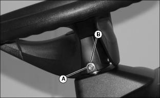
3. Install shoulder bolt (A). Drive bolt in until head of bolt contacts steering wheel.
4. Install washer and nut (B).
5. Tighten lock nut until it is snug. Do not pull washer or head of bolt into steering wheel.
Check Tire Pressure
2. Check tire pressure with an accurate gauge.
3. Check that tires have equal air pressure. Add or remove air, if necessary.
Install Mower Gauge Wheels
NOTE: Gauge wheels are located in bag of parts inside machine hood and attaching hardware is installed on mower deck for shipping. Hardware is not installed in correct hole position for operation.
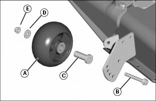
1. Install four mower gauge wheels (A) to the outside of mower brackets using one bolt (B), bushing (C), washer (D), and nut (E). (See Adjusting Mower Deck Wheels in Operating section.)
2. Tighten nut to 37 N·m (27 lb-ft.).
3. Adjust mower level before operation.
Install Grass Collector Switch
1. Install black rubber cover on collector bucket presence switch.
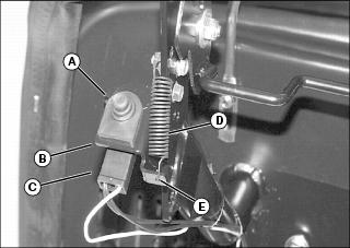
2. Install switch (A) in bracket (B) on left bucket support bracket.
3. Install connector (C) to bottom of collector bucket presence switch.
4. Install spring (D) in hole (E) of switch bracket and bucket support bracket.
Install Fill Indicator Paddle (Optional)
NOTE: This paddle improves leaf collection. Install paddle only when collecting leaves. Remove paddle when collecting grass.
If your machine does not come with this paddle, see your John Deere dealer for a Fill Indicator Paddle Kit.
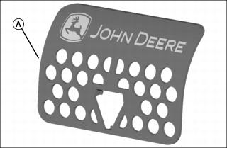
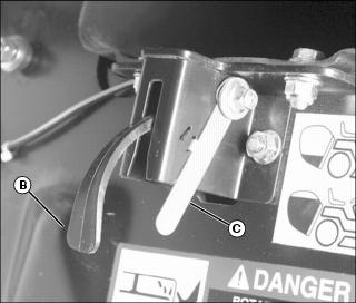
1. Press paddle (A) against front of fill sensor (B) until tabs on back of paddle snap onto sensor.
2. Adjust latch (C) if necessary to set sound signal that indicates when bucket is full. Use decal near latch as a guide in adjusting latch. (See Adjusting Grass Collector Fill in Operating section.)
Install Gas Cylinders
NOTE: The gas cylinders are strapped to the grass collector support bracket at the rear discharge opening for shipping purposes. The cotter pins and washers are in the bag of parts.
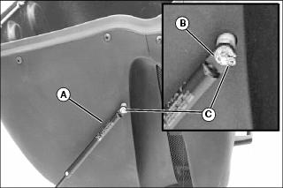
1. Fasten each gas cylinder (A), one on each side, to outside bucket pin (B) with washer and cotter pin (C) from bag of parts.
Install Grass Collector
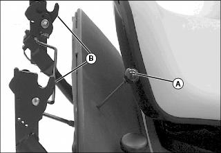
1. Pull release handle (A) out to put support brackets (B) in the unlocked (open) position.
2. Align inside bar of grass collector with open support brackets and set bar into brackets.
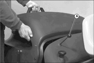
3. Push release handle (A) down to close support brackets.
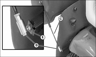
4. Attach gas cylinders (C) to tractor, one on each side, by aligning slot in fastener (D) with ball joint (E) and releasing fastener down to close.
5. Push grass collector down to close.
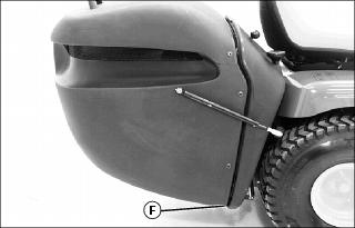
6. Check gap (F) at bottom of grass collector.
7. Adjust grass collector latches for tighter fit between grass collector and back plate if necessary.
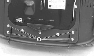
Picture Note: Grass collector removed for photo clarity
b. Remove four bolts and nuts (G) at bottom of back plate.
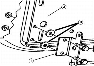
c. Install additional washers (H) between latch brackets (I), one on each side, and back plate (J).
d. Remove or add washers after use for tighter fit.
Fill Fuel Tank
IMPORTANT: Avoid damage! The fuel tank is dry when the machine is shipped. Damage may occur to the fuel pump if the machine is started without fuel. Fill fuel tank before turning on ignition key. |
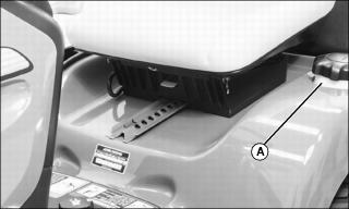
2. Fill tank with fresh fuel. Fill only to bottom of filler neck.
Check Machine Safety System
Perform safety system check to make sure the electronic safety interlock circuit is functioning properly. Perform all tests. (See Testing Safety System in the OPERATING section.)