
Assembly
Install Steering Wheel and Tilt Lever
1. Position front wheels to point straight forward.
2. Remove and discard protective cap from steering shaft.
3. Apply multi-purpose grease to steering shaft and steering wheel spline, to prevent rust.
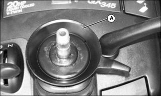
4. Install tilt lever (A) on shaft.
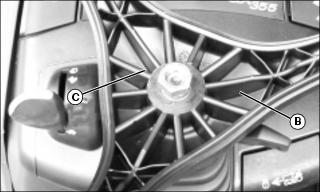
5. Install steering wheel (B) on shaft.
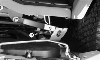
6. Install and tighten nut (C) to 20 N·m (15 lb-ft).
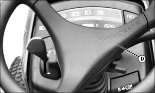
7. Install center cover (D) so John Deere name is positioned properly.
Install Plastic Front Bumper Cover
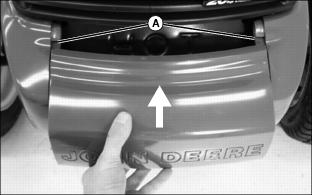
1. Slide bumper cover into slots (A).
2. Push down on front center of cover until it snaps into place.
Install Seat
1. Install seat on seat base and install hinge pin (A).
2. Install E-ring (B) onto each end of hinge pin.
Install Mower Discharge Chute
NOTE: Your mower deck may be shipped with or without discharge chute installed.
1. Hold chute firmly on mower deck when installing.
2. Install mower discharge chute to mower deck with two bolts (A) and lock nuts (B).
3. Tighten nuts to 20 N·m (15 lb-ft).
4. Check hinge action by opening and releasing the chute. The chute must spring back completely to the lowered position.
Check Tire Pressure
2. Check tire pressure with an accurate gauge.
3. Add or remove air, if necessary.
Charge and Connect Battery
1. Remove and discard the red positive (+) protective cap from the positive (+) battery terminal.
· Battery is fully charged at 12.6 volts.
3. Connect positive (+) battery cable to battery.
4. Connect negative (-) battery cable.
5. Apply general purpose grease or silicone spray to terminal to help prevent corrosion.
6. Slide red cover over positive battery cable.
Install Mower Wheels
2. Raise mower deck completely.
3. Stop machine on a level surface, not on a slope.
7. Wait for engine and all moving parts to stop before you leave the operator's seat.
8. Remove wheels from mower and install in operating position:
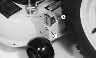
· 48 Inch Mower - Remove spring locking pin (A) and drilled pin (B). Move wheel to operating position. Install pins.
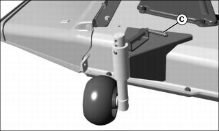
· 54 Inch Mower - Pull pin (C) outward and move wheel to operating position. Release pin to lock wheel in position.
Adjust Mower Level
NOTE: Mower wheels should not contact the ground when leveling the deck.
2. Stop machine on a level surface, not on a slope.
4. Lower mower deck completely.
7. Wait for engine and all moving parts to stop before you leave the operator's seat.
8. Disconnect the negative battery cable or remove the spark plug wire before servicing the machine.
9. Adjust cutting height to 50 mm (2 in.).
Adjust mower level (Side-to-Side)
NOTE: The difference between blade measurements must not be more than 3 mm (1/8 in.).
1. Turn left blade parallel to axle and complete measurement. Hold drive belt and turn right blade parallel to machine axle and complete measurements.
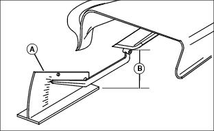
Picture Note: A convenient leveling gauge (A) is available from your John Deere dealer.
2. Measure from each outside blade tip (B) to the level surface.
NOTE: Cutting height can closely match knob setting by adjusting lift links on both sides of deck.
Picture Note: Left side shown.
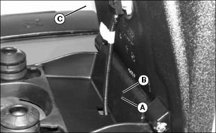
3. Adjust lift links. Turn nut (C) clockwise to raise left side of mower and counterclockwise to lower left side of mower.
Adjust mower level (Front-to-Rear)
1. Turn blades so blade tips point straight forward.
2. Measure from each outside blade tip (B) to the level surface. The front blade tips must be 3-6 mm (1/8-1/4 in.) lower than rear blade tips.
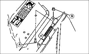
3. Adjust front-to-rear mower level if necessary:
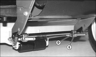
a. Loosen rear nut (D) on each side of front lift rod.
b. Turn front nut (E) on each side clockwise to raise front of mower or counterclockwise to lower it.
c. Tighten rear nuts after adjustment is complete.
4. Check adjustment by measuring blade tips again.
Break In Electric PTO Clutch
IMPORTANT: Avoid damage! Do not break-in clutch without mower deck installed. Clutch must be burnished against drive resistance of mower deck. |
1. Move machine to a hard, level surface.
4. Lower mower deck completely.
5. Move throttle lever to half speed position. Allow engine to warm 30-60 seconds.
6. Leave throttle at half speed position.
7. Engage PTO and run mower for 5 seconds.
8. Disengage PTO and wait 15 seconds for clutch to cool.
9. Repeat this cycle 15 to 20 times to properly burnish PTO clutch.
Test Safety Systems

The safety systems installed on your machine should be checked before each machine use. Be sure you have read the machine operator manual and are completely familiar with the operation of the machine before performing these safety system checks.
Use the testing procedures in the Operating section of this manual to check for normal operation of machine.
If there is a malfunction during one of these procedures, do not operate machine. See your authorized dealer for service.
Perform these tests in a clear open area. Keep bystanders away.