Assembly
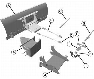
Identify Parts
MX35652
A - Blade Assembly
B - Lift Rod, Inner
C - Front Draft Pin
D - Lift Rod, Outer
E - Bracket, Rockshaft
F - Bracket, Support
G - Rockshaft
H - Bearing (2) (In bag of parts)
I - Plate, Mounting
J - Hitch, Front Attachment
K - Blade Support
Parts in Bag
Qty.
|
Description
|
2
|
Gage Wheel
|
2
|
Spring Locking Pin, 2.5 x 61.5 mm
|
1
|
Spring Locking Pin, 4.5 x 90 mm
|
2
|
Spring Locking Pin, 2.5 x 44 mm
|
2
|
Skid Shoe
|
2
|
Drilled Pin, Small, 9.4 x 25.4 mm
|
Attaching Parts Bag
Qty.
|
Description
|
4
|
Drilled Pin, 10 x 28 mm
|
4
|
Locking Ring
|
1
|
Clevis Pin, 6 x 40 mm
|
1
|
Cotter Pin, 2.5 x 16 mm
|
1
|
Cotter Pin, 3.2 x 32 mm
|
1
|
Cotter Pin, 2.5 x 20 mm
|
1
|
Capscrew, 3/4 x 5-1/2 in.
|
2
|
Nut, Jam, 3/4 in.
|
1
|
Bushing, Flange
|
1
|
Bolt, Flange, M10x30
|
1
|
Nut, Flange, M10
|
Assemble Front Blade
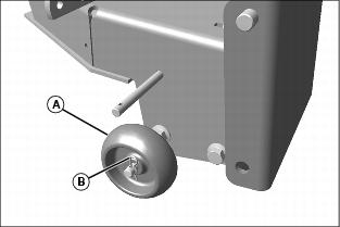
MX35655
1. Install gage wheel (A), one on each side of blade support and fasten with 2.5 x 44 mm spring locking pin (B).
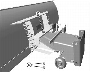
NOTE: Jam nuts (D) should be installed back to back.
MX35656
2. Fasten blade support to blade with 3/4 x 5-1/2 in. capscrew (C) and two 3/4 in. jam nuts (D).
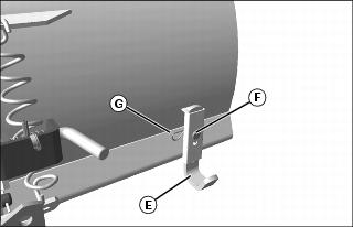
MX35657
3. Install each skid shoe (E) with small 9.4 x 25.4 mm drilled pin (F) and 2.5 x 61.5 mm spring locking pin (G).
|