
Installing
Install Lift Assembly
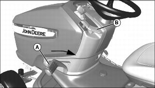
• For foot lift: Pull lift pedal (A) back by hand to lower linkage to the lower/down position. Pull lock lever (B) up to lock linkage in the lowered position.
• For hydraulic lift: Push lever (B) down to lower linkage.
2. Park machine safely. (See Parking Safely in the SAFETY section.)
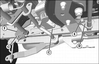
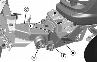
3. Raise shorter inner lift rod (C) into position and install front side of lift rod to ear of rockshaft (D). Secure with 10 x 28 mm drilled pin (E) and locking ring.
4. Install rear side of shorter inner lift rod to ear (F) of shaft. Secure with 10 x 28 mm drilled pin (G) and locking ring.
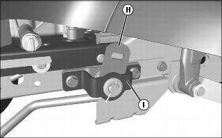
5. Verify that outside rockshaft bracket (H) does not interfere with the mounting plate (I).
• Check with attachment linkage in lower/down position.
• Check with attachment linkage in raised/up position by pushing on lift pedal and locking in raised position for foot control models. For hydraulic control models, raise linkage by pulling up on lever on dash.
• If there is interference, disconnect rear end of inner rod, and rotate yoke to shorten or lengthen rod for proper fit. Install inner lift rod and repeat as necessary.
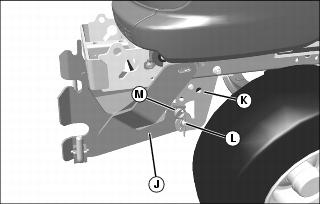
6. Align hole in front attachment hitch (J) with hole in front draft assembly (K) and install front draft pin (L). Secure with large 4.5 x 90 mm spring locking pin (M).
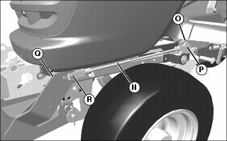
7. Install rear side of longer outer lift rod (N) onto rockshaft bracket (O) with 10 x 28 mm drilled pin (P) and locking ring.
8. Install front side of longer outer lift rod onto lift lever bracket (Q) with 10 x 28 mm drilled pin (R) and locking ring.
Install Blade

• For foot lift: Push down slightly on foot pedal (A) and push down on lock lever (B) to unlock latch; pull foot pedal towards rear of machine to lowered position, and pull up on lock lever to lock blade into lowered position.
• For hydraulic lift: Push lever (B) down to lower blade.
2. Align blade and blade support (C) with front attachment hitch (D).
3. Secure blade support pins (E) onto top slots in front attachment hitch.
4. Pull L-pins (F), on each side, outward and lower blade mount bracket. Release L-pins and lock into place.
NOTE: If blade cannot be locked in the up position, decrease blade lift height.
• For foot lift: Pull up slightly on foot pedal (A) and push down on lock lever (B) to unlock latch; push foot pedal all the way down (towards front of machine), and pull up on lock lever to lock blade into raised position.
• For hydraulic lift: Pull lever (B) up to raise blade.
6. Move two gage wheels to the storage position and secure with spring locking pins (G).