Assembly
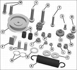
Identify Parts - Bag of Parts
MX36221
Qty.
|
Description
|
1
|
Spring (A)
|
2
|
Locking Ring (Pins to yoke) (B)
|
2
|
Washer, 13x37x3 (C)
|
1
|
Washer, 38x26x1.2 (D)
|
2
|
Pin, Drilled (Yokes to lift linkage) (E)
|
1
|
Guide, Belt (F)
|
1
|
Sheave, Idler (G)
|
2
|
Spacer, Center Mounting (19 OD x 27) (H)
|
5
|
Locknut, M12 (I)
|
1
|
Locknut, M8 (Primary belt sheave) (J)
|
1
|
Locknut, M8 (Stop on lift arm) (K)
|
1
|
Spacer, Shorter Pivot (19 OD x 12) (Left rear mount) (L)
|
1
|
Spacer, Longer Pivot (19 OD x 17) (M)
|
1
|
Bushing, Outer (Lift arm to tractor, manual only) (N)
|
1
|
Bushing, Inner (Lift arm to tractor, manual only) (O)
|
2
|
Spacer, 16 OD x 15 (long spacer on front mount) (P)
|
1
|
Bushing, (Lift Arm to Tractor) Hydraulic only (Q)
|
1
|
Bolt, M12x25 (R)
|
1
|
Bolt, M8x20 (Stop on lift arm) (S)
|
1
|
Bolt, M8x50 (Primary Belt Idler) (T)
|
1
|
Bolt, M12x70 (Right rear mount) (U)
|
1
|
Bolt, M12x65 (Left rear mount) (V)
|
2
|
Bolt, Socket Head (W)
|
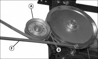
Install Idler Sheave
M97634
1. Position idler sheave (A) and belt guide (B) onto tensioning arm (C). Make sure shoulder (D) of sheave bushing is seated against the belt guide.
2. Install M8x50 flange bolt (E) from bottom side of idler sheave. Install M8 locknut at top side of sheave. Do not tighten completely.
MX35343
3. Route belt (F) between belt guide (B) and idler sheave (A).
4. Adjust the position of belt guide (B) as shown. Make sure belt guide does not contact idler sheave.
NOTE: Make sure belt guide does not move out of position when tightening locknut.
5. Hold bolt head (E) with wrench and tighten M8 locknut completely at top side of idler sheave.
6. After tightening, make sure the idler sheave rotates freely on the tensioning arm.
7. Pull the belt tight and make sure belt guide does not contact idler sheave or belt.
|