
Preparing Vehicle
Check Tire Pressure
Inflate tires to correct pressure (See tractor operator manual for various tire inflations).
Machine Setup
NOTE: Parts installed during preparing vehicle do not need to be removed and can remain on tractor.
Remove Mower Deck
The mower deck must be removed from your tractor before installing the tiller. See your tractor operator’s manual or mower deck manual for removal instructions.
Remove any attachments
Attachments if installed on tractor must be removed from your tractor before installing the tiller. See your tractor operator’s manual or attachment manual for removal instructions.
Remove Fender Deck
NOTE: Fender deck removal only needs to be done for the first time the tiller is installed.
1. Park machine safely with park brake locked. See “Parking Safely” in the Safety section.
2. Raise hood. Disconnect negative battery terminal.
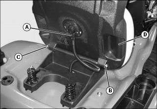
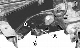
3. Disconnect seat switch wiring connector (A) from seat switch.
4. Remove the retaining ring (B) and pivot pin (C). Remove the seat (D).
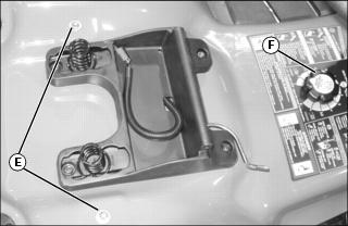
5. Remove the two bolts (E) from the top of the fender deck.
6. Remove the deck height adjustment knob (F).
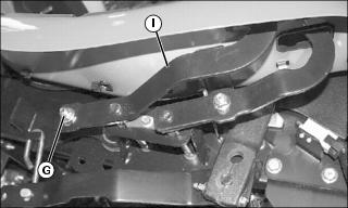
7. Remove nut (G) from reverse pedal (H). Remove pedal.
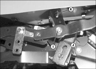
8. Remove nut (I) from forward pedal (J). Remove pedal.
9. Remove nuts (K) securing each side of the fender deck to the support brackets.
10. Remove the fuel tank filler cap.
11. Remove fender deck, being careful to guide seat switch wiring through hole in bottom of fender deck.
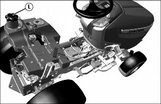
12. Immediately install fuel tank filler cap (L), being sure to not allow dirt or other debris to enter fuel tank.
Install Center Mounting Pin
1. Install center mounting 16 OD x 15 spacer (A) onto socket head screw (B) and secure to the side of frame with an M12 nut (C). Repeat on the other side of frame. Tighten to 80 N•m (58 lb ft).
Install Rear Weight Retaining Bolts
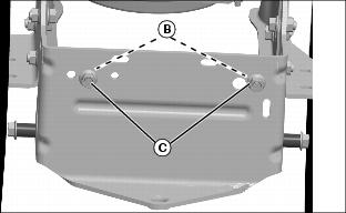
1. Install two M12x25 bolts (B), with bolt heads facing the inside of the tractor. Fasten with two M12 locknuts (C).
Install Rear Frame Mounting Hardware
IMPORTANT: Avoid damage! Be sure there is no interference with other linkage when installing the rear lift bracket. |
NOTE: The 19 OD x 12 bushing (H) used on the left side is shorter then 19 OD x 17 bushing (E) used on the right side.
The boss (I) on the lift bracket is on the left side of the machine.
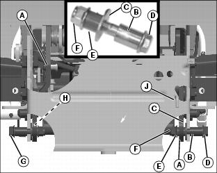
1. Install rear lift bracket (A) through bottom of hitch plate and tow valve linkage (J).
2. Install M12x70 bolt (D) through 19 OD x 27 spacer (B), through the outside of right frame and then through M13x37 washer (C).
3. Continue installing the M12x70 bolt through the lift bracket (A) and install the longer 19 OD x 17 bushing (E) on the threaded end of the bolt from the inside and secure with M12 locknut (F).
4. Repeat on left side except the bolt is a M12x65 (G) and the pivot bushing (H) is the smaller 19 OD x 12 bushing.
5. Tighten to 105 N•m (78 lb-ft).
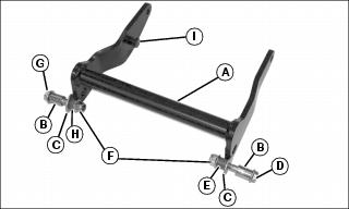
Prepare Hydraulic Lift Assembly
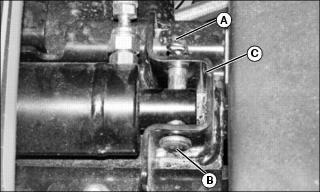
1. Remove the spring locking pin (A) and slide the drilled pin (B) back through the first leg of the cylinder attaching bracket (C).
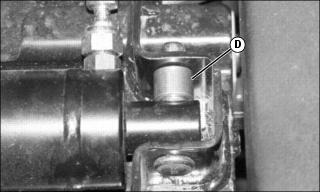
2. Install the 19 OD x 15.3 spacer (D) onto the drilled pin and attach the spring locking pin.

3. Remove and retain nut (E) and slide bolt (F) just enough to remove and retain spacer (G).
4. Remove and discard spacer (H).
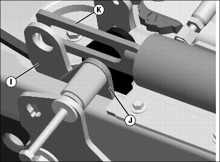
5. Install lift arm (I) between connector bracket (J) and cylinder rod (K) by sliding the lift arm inside the frame from the rear of the tractor.
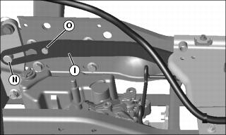
6. Install the slotted end of the lift arm (I) to the rear of the tractor onto the lift bracket boss (N).
7. Install M8x20 bolt (O) to the lift arm (I) from the inside and install M8 nut on the bolt, this acts as a stop for the boss (N) on the lift bracket.
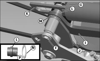
8. Install the larger OD boss hydraulic lift spacer (L) with side (P) of the spacer through the lift arm (I) from inside out and install 38x25.8x1.2 washer (M) onto spacer against outside surface of arm (I), while sliding the bolt through these items.
NOTE: Be sure while tightening hardware the washer remains on the boss and does not come off.
9. Install smaller OD spacer (G) removed earlier after the cylinder rod and continue sliding bolt (F) through and secure with nut (E) removed earlier. Tighten to 60 N•m (45 lb-ft).
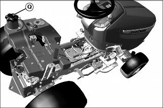
10. Remove the fuel tank filler cap (Q).
11. Install fender deck, being careful to guide seat switch wiring through hole in bottom of fender deck.
12. Immediately install fuel tank filler cap, being sure to not allow dirt or other debris to enter fuel tank.
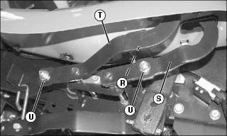
13. Install nuts (R) to secure each side of the fender deck to the support brackets.
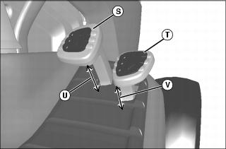
14. Install forward (S) and reverse pedals (T), and secure with nuts (Q). Do not tighten nuts.
15. Measure distance (U) for forward pedal and distance (V) for reverse pedal.
• X300s: Forward pedal distance should be 56 distance should be 41
• X500s: Forward pedal distance should be 48 distance should be 33
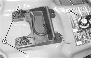
16. Install the deck height adjustment knob (W).
17. Install the two bolts (X) to secure the top of the fender deck.
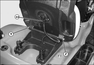
18. Install the seat and secure with seat pivot pin (Y) and retaining ring (Z).
19. Install seat switch wiring connector (aa) onto seat switch.