
Operating
Daily Operating Checklist
o Remove grass and debris from engine compartment, muffler area, and front grille, before and after operating machine.
o Check area below machine for leaks.
o Check brakes and park brake operation.
o Check air restriction indicator.
Avoid Damage to Plastic and Painted Surfaces
· Do not wipe plastic parts unless rinsed first.
· Insect repellent spray may damage plastic and painted surfaces. Do not spray insect repellent near machine.
· Be careful not to spill fuel on machine. Fuel may damage surface. Wipe up spilled fuel immediately.
Operator Station Controls

A - Cargo Box Power Lift Switch (Optional)
C - Engine Coolant Temperature Light
H - Hazard Lights Switch (Optional)
I - Front Blade Lift/Lower Switch (Optional)
L - Choke Knob (Models with choke on dash)
M - Turn Signal Switch (Optional)

Picture Note: Seats removed for clarity.
B - Choke Knob (Models with choke under seat)
G - All Wheel Drive (AWD) Lever
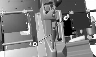
Using Hand Holds

Hand holds are provided for passenger balance. When a passenger is present, they shall use two of the three hand holds at all times while the machine is moving. The dash bar (A), side rail (B), and grab handle (C).
Adjusting Operator's Seat
1. Stop machine and move transaxle shift lever to N (neutral) position.

Picture Note: Seats removed for clarity.
3. Push lever (A) to the left.
4. Slide seat forward or rearward to desired position.
Adjusting Passenger Seat

Picture Note: Rear position shown.
2. Hold onto seat and remove cap screws (A).
3. Slide seat to the forward (B) or rearward (C) position.
4. Position bottom of seat against bracket and align correct holes with holes in seat.
5. Install original hardware to secure seat.
6. Tighten seat bracket hardware to 10 N·m (7 lb-ft).
Testing Safety Systems

The safety systems installed on your machine should be checked before each machine use. Be sure you have read the machine operator manual and are completely familiar with the operation of the machine before performing these safety system checks.
Use the following checkout procedures to check for normal operation of machine.
If there is a malfunction during one of these procedures, do not operate machine. See your authorized dealer for service.
Perform these tests in a clear open area. Keep bystanders away.
Testing the Safety Start System
1. Sit on the operator's seat.
2. Put key switch in OFF position.
4. Move transaxle shift lever forward to the high range position.
5. Turn key switch to start position. Engine should not crank. Turn key switch off.
6. Move transaxle shift lever to reverse position.
7. Turn key switch to start position. Engine should not crank. Turn key switch off.
Using Park Brake
Always lock the park brake and remove the key before leaving the machine unattended. |
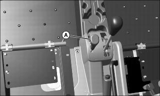
Locking the Park Brake:
Picture Note: Seats removed for photo clarity.
1. Push down on brake pedal to hold machine in place.
2. Pull up on lever (A) and lock lever into position engaging park brake.
Unlocking the Park Brake:
1. Push down on brake pedal to hold machine in place.
4. Release lever down completely.
Using Key Switch
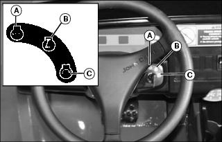
A - OFF Position - With key in off position, all switched power is off, and engine should not run.
B - ON Position - Turn key from off to this position and all switched power circuits will be energized.
C - START Position - Turn key to start position to start the engine. Release key after engine has started and it will automatically return to the on position. The engine will continue to run.
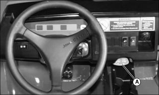
Using Headlights
Key switch must be in the run position to operate the lights. If the key switch is in the run position and the engine is not running, the battery will discharge if the lights are allowed to remain on for an extended period of time.

· Press at top of light switch (A) to turn headlights on.
· Press at bottom of light switch (A) to turn headlights off.
Using and Checking Instrument Panel
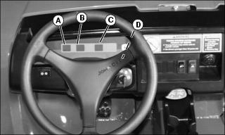
A - Engine Oil Pressure Light - This light will turn on when the ignition key is in the ON position and the engine is not running. If this light turns on while the engine is running, engine oil pressure is too low. Stop engine.
B - Engine Coolant Temperature Light - This light will turn on when the ignition key is in the START position and the transmission is in neutral. The light will turn off when the key is released to the ON position. This light will turn on when the engine coolant is approaching a dangerously hot temperature. If this light turns on during operation, remove load on machine immediately. Stop engine, move transaxle shift lever to neutral, and lock park brake. Check for something blocking air flow to the radiator and check engine coolant level.
C - Park Brake Light - This light will turn on when the key switch is in the ON position and the park brake is locked.
D - Hour Meter - The hour meter operates and displays when the engine is running. The hour meter shows the accumulated number of hours the engine has run. The hour meter is intended to provide a means of monitoring machine usage for maintenance purposes. Use the hour meter to determine when your machine has reached the recommended service intervals.
Using Accessory Outlet
NOTE: Accessory must be rated at 10 amps or less.
The accessory plug does not turn off with the key switch. Items connected to the accessory plug will continue to draw power draining the battery.
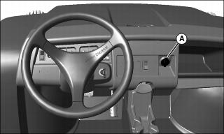
· Remove 12-volt outlet (A) cover and install accessory cord in outlet.
· Install cover in outlet after use.
Using Turn Signal Switch (Optional)
NOTE: Turn signals will continue to flash when the key is in the off position, draining the battery.
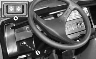
· Press at left end of turn signal switch (A) to signal a left turn.
· Press at right end of turn signal switch (A) to signal a right turn.
· Press at opposite end of turn signal switch (A) until switch is centered to turn signal light off.
Using Hazard Lights (Optional)
NOTE: Hazard lights will continue to flash when the key is in the off position, draining the battery.
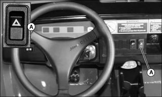
· Press at top of hazard light switch (A) to turn hazard lights on.
· Press at bottom of hazard light switch (A) to turn hazard lights off.
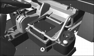
Using Storage Tray

Storage tray (A) is located in front of machine under the hood. This is a convenient location to carry personal articles such as an Operator's Manual, spare parts, first aid kit, and/or tools. The storage tray has a total volume of 7210 cc (440 in.3).
1. Open hood to access the storage tray.
2. Secure all items to prevent damage from movement while operating the machine.
Starting the Engine
1. Sit on operator seat. Do not start engine at this time.
2. Push down on accelerator pedal to check free movement of pedal assembly. Release pedal.
NOTE: The machine has a neutral start safety switch. The engine will not start unless the transaxle shift lever is in N (Neutral) position.
3. Verify that transaxle shift lever is in N (Neutral) position.
4. Verify that park brake is locked.
5. Turn key switch to the ON position.
6. Check that the oil pressure indicator light is on.
Picture Note: Model with choke under seat.
(Seats removed for clarity.)
· Models with choke under seat: Pull out and hold choke knob (A) if engine is cold. The choke spring will return the choke to the open position when released.
IMPORTANT: Avoid damage! Open the choke by pushing the knob in to its full off position as soon as possible. Running the engine with the choke on beyond the warm up period may lead to plug fouling. |
NOTE: The dash mounted choke is designed with a snap-and-seal option that can be used for maximum weather protection during pressure washing or stormy weather. Under normal use this feature does not need to be used. To use this option, push in choke until it snaps or clicks and can be pushed in no further.

Picture Note: Model with choke on dash.
· Models with choke on dash: Pull out fully on the choke knob (A) if engine is cold.
8. Turn key to start position.
9. Choke on dash models: Push choke in as far as needed to obtain a stable engine idle. Once engine is running smoothly, push choke all the way in (stopping before it clicks or snaps).
IMPORTANT: Avoid damage! Starter may be damaged if starter is operated for more than 20 seconds at a time: · Wait two minutes before trying again if engine does not start. |
10. Release key to the ON position when engine starts.
· If engine does not start within five seconds, turn key to off and wait ten seconds before trying to start again.
· In very cold conditions, attempt starting engine three times only, then wait 5 minutes before trying again. This will allow time for starter to cool and prevent damage to starter.
IMPORTANT: Avoid damage! Do not operate the engine at full throttle or under load until engine has warmed up, or engine damage could occur. |
11. Run engine at half speed for 2 or 3 minutes to warm the engine.
Stopping Engine
Always lock the park brake and remove the key before leaving the machine unattended. |
IMPORTANT: Avoid damage! Do not stop engine immediately after hard or extended operation. Keep engine running at low idle for about 2 minutes to prevent heat build-up. |
2. Move transaxle shift lever to N (Neutral) position.
4. Turn key switch to OFF position.
Using Travel Controls
2. Allow engine to come to a low idle speed.
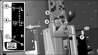
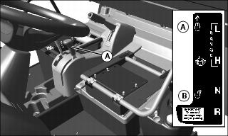
· Forward - Push shift lever forward to either high (A) or low (B) range.
· Reverse - Push shift lever to left, then pull rearward to reverse (C) gear.
4. Use the traction assist and/or AWD as needed.
5. Look in the direction the vehicle will travel.
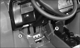
6. Push down accelerator pedal (D) slowly and smoothly to begin machine travel.
7. Release accelerator and apply brake pedal (E) evenly and firmly to slow down or stop.
Using Traction Assist
Traction Assist (A) provides better traction when rear wheels start to slip. Engaging the traction assist will cause both rear wheels to turn together at equal speed.
Engaging the Traction Assist:
IMPORTANT: Avoid damage! Incorrectly engaging traction assist may damage the transaxle. Reduce speed before engaging or disengaging traction assist. |
1. Stop or reduce engine speed to 1\3 throttle or less.
2. Push traction assist lever forward to locked position (A):
· Traction assist will remain engaged as long as lever is forward.
Disengaging the Traction Assist
NOTE: To ensure true disengagement of traction assist, you must equalize torque on both axles.
1. Stop or reduce engine speed to 1/3 throttle or less.
2. Drive the vehicle straight ahead at a constant speed.
3. Pull lever rearward to unlocked position (B).
Using All Wheel Drive (AWD) - HPX 4x4 and Trail HPX 4x4
All Wheel Drive (AWD) enables the powertrain to drive the front wheels in addition to the rear wheels for improved traction on difficult ground conditions.
NOTE: It may be necessary to reduce engine load to disengage all wheel drive.
· Machine shall be stopped or coasting in a straight line to engage and disengage AWD.
· Pull up on AWD lever (A) to engage front wheel drive system.
· Push down on lever to disengage the system.
Tips for operating AWD:
· Maintain recommended front and rear tire pressures to ensure optimum performance on all surface conditions.
· Disengage AWD when driving machine on paved or hard packed surfaces to increase front tire life and reduce drive train wear.
Raising and Lowering Cargo Box
Manual Lift
1. Park the vehicle safely. (See Parking Safely in the SAFETY section.)
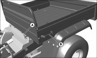
3. Release latch (A) by pushing inward toward center of machine. Raise cargo box manually with lift handle (B) on side of cargo box.

4. Push support rod (C) down to lock into slot (D) when cargo box is fully raised.
5. To lower cargo box, raise cargo box slightly using lift handle.
6. Release support rod from latch slot by pulling up on lower end of rod.
NOTE: Lowering the box completely will allow the support rod to latch at the front of cargo box.
7. Slowly lower cargo box. Support rod will slide along slotted channel.
8. Push down on cargo box handle until support rod latches into cargo box with an audible snap.
Power Lift (Optional)
1. Park the vehicle safely. (See Parking Safely in the SAFETY section.)

3. The cargo box switch (A) is located on the left side of the instrument panel.
4. Raise cargo box by pressing and holding top of switch (A). Release switch when box is at desired dump height or when reaching maximum height.
NOTE: Allowing the Power Lift hydraulics to operate at pressure relief briefly (less than one second) after cargo box is fully lowered will help keep cargo box secure and reduce rattling caused by travel vibrations.
5. Completely lower cargo box by pressing and holding bottom of switch (A).
Emptying Cargo Box

1. Back up vehicle to dump, site.
2. Park the vehicle safely. (See Parking Safely in the SAFETY section.)
NOTE: If power lift system will not lift load, lower cargo box completely and remove excess load by hand before dumping.
4. Raise cargo box to dump load.
5. Lower cargo box when empty.
6. Latch tailgate closed. Do not drive vehicle with cargo box in raised position.
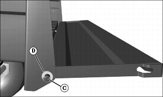
Operating the Tailgate

1. Push in and down on loop (A) of tailgate latch rods to unhook rods from slot (B) in tailgate.
2. Pull latch rods out and down.
3. Lower tailgate until it rests on ends of latch rods (C).
IMPORTANT: Avoid damage! Do not drive vehicle with tailgate unsupported and hanging down. Lugs on tires will contact tailgate causing structural damage. |
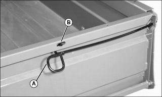
4. To raise tailgate, slowly push tailgate upward. Push inward and upward on loop (A) of latch rod to engage rod in slot (B) in tailgate.
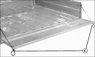
Removing Tailgate

1. Remove and retain rubber hose sleeves from latch rod ends (A).
2. Raise tailgate slightly and rotate latch rods to disengage from slots (B) in cargo box sides.
3. Remove latch rods from sides of tailgate.
5. Remove retaining ring (C) and bushing (D) from each tailgate rod end.
6. Slide tailgate sideways so tailgate rod end is clear of the cargo box bracket.
7. Pull the detached end of tailgate away from the cargo box just enough to clear the cargo box bracket and allow the tailgate to slide in opposite direction to complete removal.
8. To install, reverse the steps.
Installing Tailgate Latch Rods
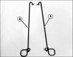
1. Identify right (A) and left (B) latch rods.
Picture Note: Left side shown.
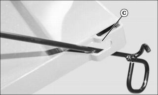
2. Route latch rod through tailgate opening (C) as shown.
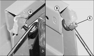
3. Raise tailgate slightly from horizontal position. Insert end of latch rod through slot (D) in cargo box bracket. Rotate rod around the bracket to secure.
4. Install rubber hose sleeve onto rod end (E).

5. Raise tailgate, push inward and upward on latch rod to engage rod in slot (F) in top rail.
Loading the Cargo Box
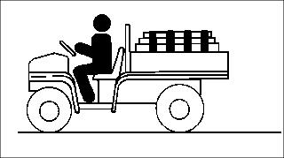
Maximum payload capacity on level terrain for the cargo box is 408 kg (900 lb).
Reduce load by half when operating over rough, hilly, or steep terrain. Do not overload vehicle. Limit loads to those that can be safely controlled.
Reduce speed and exercise extreme caution when operating over rough, hilly, or steep terrain.
Securely anchor and evenly distribute loads in cargo box, when loading objects into vehicle. Shifting loads will affect stability.

Avoid concentrated loads at rear or side of cargo box to prevent vehicle from tipping over. Be sure load is evenly distributed.
Because there is a big difference in weight between dry and wet sand, the only way of getting true weight of the load you are carrying is by using a scale.
For example, dry sand weighing 250 kg (550 lb) would be approximately 1/2 of cargo box volume.
Printed weight is normally on bagged and other material.
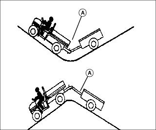
Towing Loads
· To provide adequate braking ability and traction, weight of towed load (trailer plus cargo) must never exceed the vehicle payload (operator plus passenger plus cargo box load).
· Do not tow a load that exceeds the maximum allowable towing load for this vehicle, as specified in this operator's manual.
· Do not tow a load that exceeds 590 kg (1300 lb).
· Do not exceed a tongue weight of 59 kg (130 lb).
· Tow load at a speed slow enough to maintain control.
· Always use approved hitch and hitch point provided for the utility vehicle. DO NOT modify the hitch or hitch point in any way.
Using Correct Tires and Inflation
Tires
Use of John Deere approved original equipment or optional equipment is recommended. To ensure maximum machine performance and ride quality, do not mix size, type, or placement of tires. Failure to place tires per the guidelines could result in reduced machine performance, diminished traction and poor handling.
All Trail II tires
· 24x9.5-10 tires installed on front.
· 24x10.5-10 tires installed on rear.
AT489 tires
· 24x9.5-10 tires installed on front.
· 24x12.0-10 tires installed on rear.
These are directional tires. Directional type tires have directional arrows located on the tire sidewall. These tires should be installed with the directional arrow pointing in the forward direction of travel.
Turf Trac RS tires
· 24x9.5-10 tires installed on front.
· 24x12.0-10 tires installed on rear.
Inflation
IMPORTANT: Avoid damage! Over inflation may damage tires and diminish ride quality. Under inflation could cause wheel damage when riding over rough terrain. |
NOTE: Improper tire pressure can make it difficult to disengage AWD.
An accurate low pressure gauge is available at your John Deere dealer.
2. Check tire pressure with an accurate gauge.
3. Add or remove air, if necessary.
Tire Chains
IMPORTANT: Avoid damage! Loose tire chains can cause machine damage. Periodically check chain tightness and adjust as necessary. |
Chains are available for all four wheels from your John Deere dealer.
Transporting Vehicle
NOTE: Space limitations may vary from one truck manufacturer to another. Short bed trucks do not have the necessary length requirement to accommodate the machine.

1. Drive utility vehicle onto the trailer or truck.
2. Leave transaxle shift lever in forward or reverse gear.
3. Park vehicle safely (See Parking Safely in the SAFETY section.)
4. Fasten vehicle to trailer or truck with straps, chains, or cables.
5. Equip the trailer or truck with all the necessary lights and signs required by local, state, provincial, or federal laws.