
Operating
What is Thatch
Thatch is a layer of stems, clippings and leaves that has not decayed. Thatch builds up between the ground surface and the green part of grass.
Excessive thatch, 12.7 mm (1/2 in.) or more, prevents proper amounts of air, water and fertilizer from reaching grass roots. Excessive thatch may also kill grass, provide a favorable environment for insects and encourage plant disease.
Main Cause of Thatch
A small amount of thatch is beneficial to lawns because it protects roots from direct sunlight, yet allows air, water and fertilizer to reach roots.
Decaying thatch also acts as fertilizer to promote grass growth. However, decay of grass clippings is a slow process. Thatch build-up can occur by over-fertilization, resulting in fast plant growth and more frequent mowing.
NOTE: Not all grass clippings are picked up when mower bagging attachment or lawn sweeper is used.
With a slow decaying process, a layer of thatch can build up enough to smother the grass root system.
When to Use Thatcher
Every lawn is different, so there is no rule for when to use the thatcher (which actually de-thatches, or loosens thatch so it can be removed from lawn). In general, the thatcher should be used more often on very dense lawns.
Consult your local agriculture extension service to determine when and how often to de-thatch lawn.
Ground conditions should be dry to help prevent damage to grass root system.
Summer de-thatching is not recommended.
Using Thatcher to Seed
Thatcher can be used as a scarifier to scratch new ground to seed, or an established lawn to reseed.
Lower tines 6.4 mm (1/4 in.) at a time until, when operating, tines stay in their rearward working position, scratching ground and producing a good seedbed for seeds to germinate.
Do Not Modify Thatcher
Unauthorized modifications of thatcher may impair its function or safety, and reduce thatcher longevity.
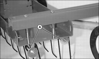
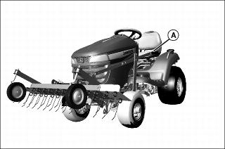
Retention safety rods (A) prevent loose or broken tines from falling into mower path. Do not alter or remove any part of tine retention safety rods. If retention safety rods break or become removed from thatcher, replace rods with parts from dealer before continuing thatcher operation.
Using Lift Handle
To Raise Thatcher:
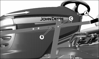
• Pull lift handle (A) toward rear of machine until notch (B) locks on drilled pin (C).
To Lower Thatcher:
• Grasp lift handle (A) firmly and raise upward until notch (B) unlocks from drilled pin (C).
• Slowly lower thatcher to ground.
Adjusting Gauge Wheels
The height of gauge wheels determines operating depth of thatcher.
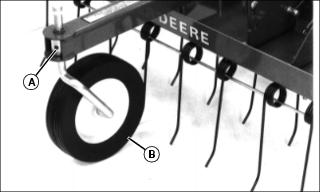
1. Loosen set screw (A) with hex wrench to adjust gauge wheel (B) height.
2. Tighten set screw (A) at desired depth setting.
Adjusting Tine Action
Grass should be less than 76.2 mm (3 in.) tall for proper tine action.
When in use, all tines on thatcher should deflect back independently and flip thatch forward.
• In free position (A), tines are relaxed and not working.
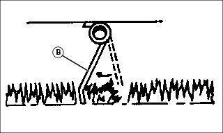
• In thatching position (B), tines are rearward and working.
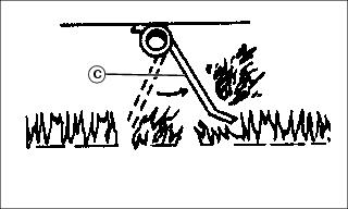
• In released position (C), tines are flipping thatch up, ready to be picked up by mower/bagger or sweeper.
Thatching
• Set thatcher tines in released position (C) to loosen thatch for removal from lawn.
• If tines remain in thatching position (B) where they work but do not flip thatch up, raise main frame.
• If tines remain in free position (A) where they do not work or lift thatch, lower main frame.
Seeding
• Set thatcher tines to remain in thatching position (B) to seed or reseed lawn.
Leveling Thatcher
NOTE: Level thatcher only when installed on tractor.
1. Park machine safely. (See Parking Safely in the SAFETY section.)
2. Lower thatcher slowly to ground by lifting and slowly releasing lift handle (A).
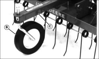
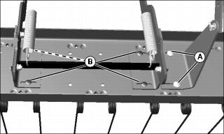
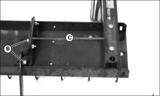
3. Align each gauge wheel (B) directly under wheel support (C).

4. Loosen mounting frame nuts (D) securing thatcher to mounting frame.
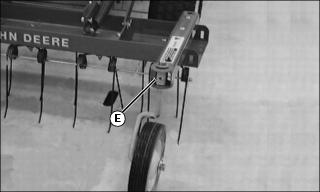
5. Loosen set screw (E) on each gauge wheel.

6. Adjust height of thatcher frame (F) so both tine rows (G) are approximately 12.7 mm (1/2 in.) above the ground in the free position. Tines should touch flat surface when manually deflected rearward.
7. Tighten mounting frame nuts (D) and gauge wheel set screws (E).
8. Operate thatcher in lawn after initial leveling and centering adjustments. Make further leveling adjustments only 6.4mm (1/4in.) at a time. Reminder: adjust tines to released position to loosen and flip up thatch for removal by mower/bagger.
Centering Thatcher
NOTE: Center thatcher only when installed on tractor.
1. Park tractor on level surface, not on slope.
2. Disengage power take-off (PTO).
5. Wait for engine and all moving parts to stop.
7. Lower thatcher slowly to ground by releasing lift handle.
8. Loosen carriage bolts (A) and (B) so lift handle bracket and frame mounting brackets can slide in adjustment slots.
9. Adjust thatcher by sliding frame mounting brackets left or right in adjustment slots. Keep distance (C) between gauge wheel support and mounting bracket equal on both sides of thatcher.
10. Tighten carriage bolts (B) on frame mounting brackets.
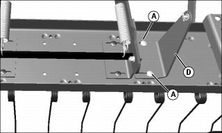
11. Align lift handle bracket (D) so lift handle remains straight as it leaves lift lock extension mounted at tractor frame. Tighten carriage bolts (A).
Checking Thatcher Tines
A broken tine can be picked up and thrown by mower.
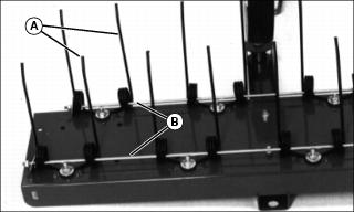
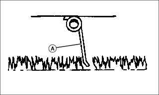
1. Check tines (A) on entire unit for breaks or cracks. Replace broken or cracked tines with parts from dealer.
2. Make sure retention safety rods (B) pass through all tines and are secured at ends with washer and locknut.
Transporting Thatcher
When transporting, lock thatcher in the transport position.
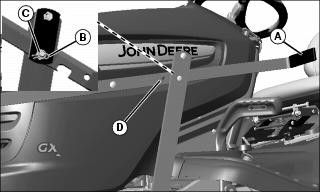
1. Pull lift handle (A) toward rear of tractor
2. Remove the spring locking pin (B) and drilled pin (C).
3. Align the hole (D) from lift handle and lift lock extension and install drilled pin.