
Assembly
Thatcher Assembly
NOTE: Thatcher Frame Extensions are used for increasing thatching width for the 38 in. thatcher and for making the 46 and 54 in. thatcher:
• 46 in. Thatcher: use one frame extension.
• 54 in. Thatcher: use two frame extensions.
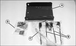
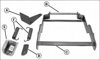
Identify Parts - Thatcher Main Frame

Box of Parts
Bag of Parts
Identify Parts - 8 in. Frame Extension
Box of Parts
Bag of Parts
Assemble Thatcher (38 and 54 in.)
Attach Mounting Brackets
|
• Tines are sharp. Wear heavy gloves when working around tines. • Do not work under raised attachment unless it is safely supported. |
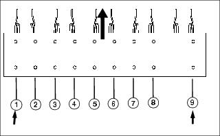
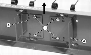
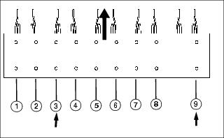
1. Locate frame mounting bracket mounting holes 4 and 7.

2. Attach frame mounting brackets (A). Long side of each bracket must face toward outside of frame as shown.
3. Install four 5/16x1 in. carriage bolts (B) and locknuts. Do not tighten completely.
Attach Wheel Assemblies
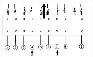
1. Locate wheel support bracket mounting holes 1 and 9.

2. Fasten wheel supports (C) to main thatcher frame using four 5/16x4 in. carriage bolts (D), pipe spacers (E), and locknuts.
Assemble Thatcher (46 in.)
Attach Mounting Brackets
|
• Tines are sharp. Wear heavy gloves when working around tines. • Do not work under raised attachment unless it is safely supported. |
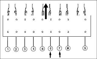
1. Locate frame mounting bracket mounting holes 4 and 7.
2. Attach frame mounting brackets (A). Long side of each bracket must face toward outside of frame as shown.
3. Install four 5/16x1 in. carriage bolts (B) and locknuts. Do not tighten completely.
Attach Wheel Assemblies
1. Locate wheel support bracket mounting holes 1 and 9.

2. Fasten wheel supports (C) to main thatcher frame using four 5/16x4 in. carriage bolts (D), pipe spacers (E), and locknuts.
Assemble Frame Extension (46- and 54-Inch Thatchers)
|
• Tines are sharp. Wear heavy gloves when working around tines. • Do not work under raised attachment unless it is safely supported. |
NOTE: The 46-inch thatcher requires installation of one extension on right side of main thatcher frame. The 54-inch thatcher requires installation of two extensions, one on each side of frame.
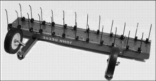
Picture Note: Finished 46-inch thatcher with one extension installed on right side of main thatcher frame.
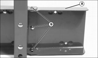
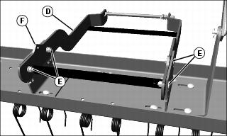
1. Install frame extension (A) on right side of main frame using three 5/16x3/4 in. carriage bolts through main frame and extension, then 0.344x.688 washers, lock washers and 5/16 in. hex nuts (B). Tighten nuts completely.
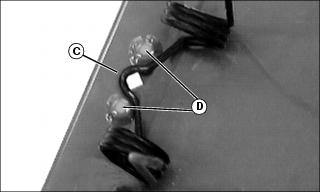
2. Position the offset (C) in tine between two frame extrusions (D).
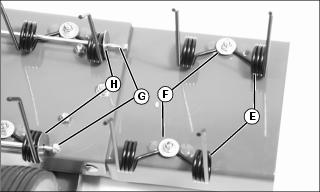
3. Attach two times (E) to extension with tine tips facing same direction as tine tips in main frame. Fasten with two 5/16x1 in. carriage bolts, 9x29x3mm washers, lock washers and 5/16 in. hex nuts (F). Tighten nuts completely.
4. Remove and retain locknuts (G) and washers (H) from main frame tine retention rods.
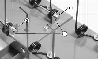
5. Install two-hole washers (I) onto main retention rods. Fasten with lock nuts (G), previously removed.
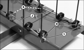
6. Place short retention rods (J) through tines and secure in two-hole washers with 1/4 in. locknuts (K).
7. Install washers (H), removed previously, onto other end of short retention rods. secure with 1/4 in. locknuts (L).
Identify Parts - Thatcher Mounting Kit
Box of Parts

Bag of Parts
Assemble Thatcher Mounting Kit

1. Position lift handle bracket (A) over holes next to frame mounting bracket (B) on left side of thatcher. Make sure lift handle bracket faces direction shown. Install two 5/16x1 in. carriage bolts (C), lockwashers, and hex nuts. Do not tighten completely.
2. Attach mounting frame (D) to frame mounting brackets with four 5/16x1 in. carriage bolts (E), lockwashers, and hex nuts. Mounting frames and frame mounting brackets should be aligned so hole in notch (F) is visible as shown. Tighten nuts completely to ease in assembly; nuts will be loosened later for leveling procedure.
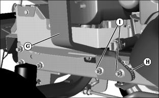
3. Install lift lock extension (G) and spacer strap (H) using existing holes in left side of tractor frame. Secure with two M10x30 flange bolts (I) and M10 serrated hex nuts. Tighten nuts completely. As nuts are tightened the heat shield will form up to proper position.
NOTE: Front of tractor indicated by (J).
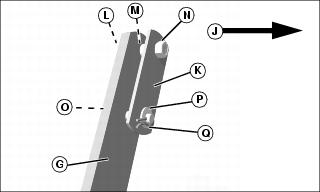
4. Assemble lock bracket (K) to the lift lock extension (G) and secure with 5/16x1-1/4 in. carriage bolt (L), spacer (M), and locknut (N).
5. Insert drilled pin (5/16x1-1/4 in.) (O) in lower hole; install washer (P) and secure with spring locking pin (Q).