
Assembly
Identify Parts
Parts in Large Box:
• Lift Handle Bracket Assembly
Parts in Small Box:
First Parts Bag (Slide Plate and Hardware)
Second Parts Bag (Locking Latch and Hardware)
Third Parts Bag (Cargo Box Latches and Hardware)
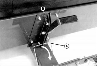
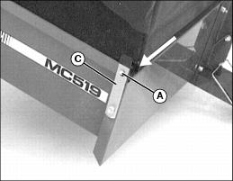
Install Lift Handle Bracket
NOTE: Tip cart box on end for ease of installation.
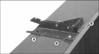
1. Place lift handle bracket (A) on MC519 cart box and fasten top part of bracket with two 5/16 x 3/4 in. hex head bolts (B), and locknuts, with locknuts to the inside of cart box. Do not tighten nuts at this time.
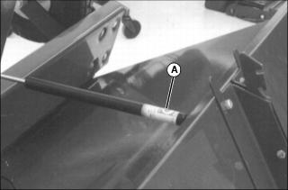
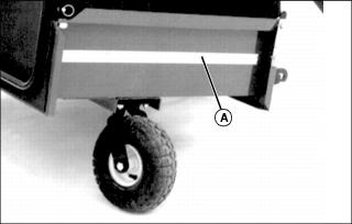
Install Drawbar Assembly
NOTE: Tip cart box flat for ease of installation
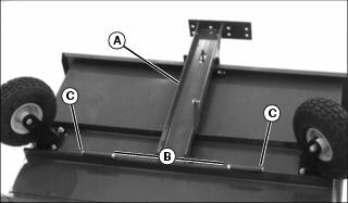
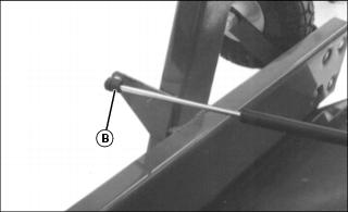
1. Attach drawbar assembly (A) to MC519 cart with two 3/8 x 4-1/2 in. hex head bolts (B) (one on each side) and locknuts (C).
NOTE: Do not overtighten nuts. Drawbar must pivot freely.
2. Tighten nuts for drawbar only.
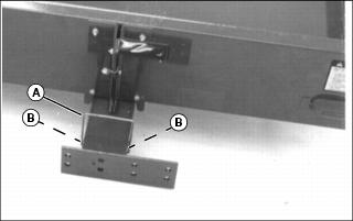
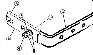
Install Gas Cylinder Bracket
NOTE: Tip cart box on end for ease of installation.
1. Install gas cylinder bracket (A) on cart, and fasten with two 5/16 x 3/4 in. hex head bolts and locknuts (B).
NOTE: Bolts go through lift handle bracket (C) first and then gas cylinder bracket (A).
2. Do not tighten nuts at this time.
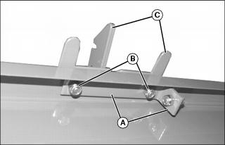
Install Latch On Drawbar
NOTE: Spread latch slightly for ease of installation.
1. Install latch (A) in holes (B) on drawbar.
NOTE: If dump cart latch does not lock in place when you push down on the cart box, adjust dump cart latch.
2. Push latch to the rear and hook on slot in lift handle.
3. Align lift bracket with drawbar, and tighten all four nuts to secure lift bracket and cylinder bracket.
Adjust Dump Cart Latch
1. Unlatch transport latch (A).
2. Loosen locknut (B). Move bolt in slot until latch locks in place.
Install Preloaded Gas Cylinder
1. Unlatch transport latch and dump latch lever.
NOTE: Tip cart box on end and open for ease of installation.
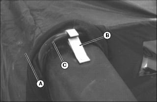
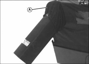
2. Install barrel end of gas cylinder (A) on ball joint closest to cart box.
3. Install rod end of gas cylinder (B) on ball joint closest to wheel assembly.
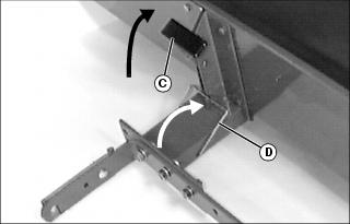
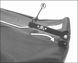
4. Push down on drawbar and latch lift lever bracket (C) to locked position.
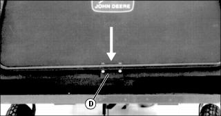
5. Push transport latch (D) in notch on lift lever bracket to locked position.
6. Return cart to the upright or operational position.
Assemble and Install QUIK-TATCH™ Bracket
NOTE: Make sure wide leg (A) of each slide plate (B) is to the top of quik-tatch bracket.
1. Assemble each slide plate (B) to the outside of quik-tatch bracket (C) with 5/16 x 1-1/2 in. carriage bolt (D) (bolt head to the inside), one washer (E), spring (F), a second washer (E), and then 5/16 in. locknut (G).
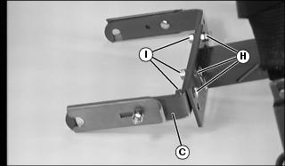
2. Install QUIK-TATCH bracket (C) to drawbar with three 1/2 x 1-1/4 in. hex head bolts (H), lockwashers and 1/2 in. nuts (I).
3. Finger tighten nuts until proper cart location is determined.
Assemble Tailgate
NOTE: Do not install tailgate when using MC Cart cover.
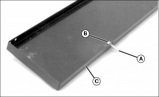
1. Install two tailgate pins (A) lockwashers and hex nuts (B) in tailgate (C) at dimpled holes.
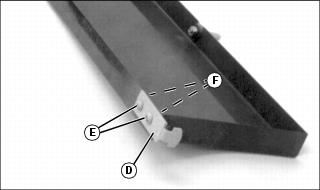
2. Install latch (D) (one on each side of tailgate) with two 1/4 x 1/2 in. round head screws (E), lockwashers and hex nuts (F).
4. Raise cargo box onto wheels.
5. Install tailgate (on cart box) by putting tailgate pins (G) into holes in cart box.
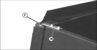
6. Put latches (H) in slots (I) on dump cart.
Install Locking Latch To Cart
NOTE: Bolt goes through hole closest to top of cart, and tab on latch goes in bottom hole on cart.
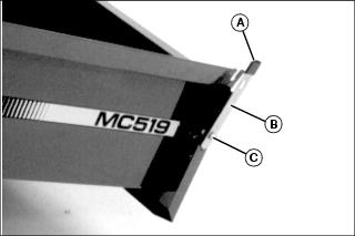
1. Install vinyl cap (A) on latch.
2. Install locking latch (B) on cart with one 5/16 x 3/4 in. hex head bolt (C), and locknut.
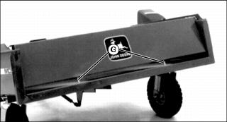
Remove Protective Covering From Decals On Cart Box
Remove protective covering (A) from decals located on both sides of cart box.
Assemble Cover
NOTE: For ease of installation, place bagger on its side.
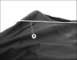
1. Push front support rod (A) to the inside of cover.
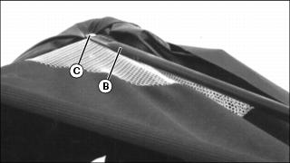
2. Install one end of side support tubing (B) on front cover support.
NOTE: Make sure bolt goes through mesh material (under cover flap) and support rod under cover. Put locknut to the inside of cover.
3. Fasten with one 1/4 x 1-1/2 in. carriage bolt (C) and locknut.
NOTE: Do not overtighten nut. Side support tubing must pivot freely to collapse cover.
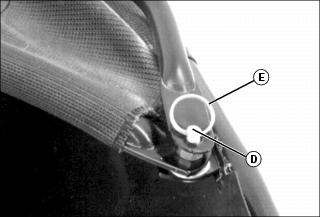
5. Install other end of side support tubing on stud (D), and fasten with spring locking ring (E).
6. Repeat Steps 2 - 5 for other side of front cover.
Install Cover Latch Bracket
NOTE: Make sure bolt goes through frame and slits in cover. Put locknuts to the inside of cover.
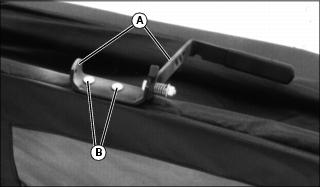
1. Install lift bracket (A) on cover, and fasten with two 1/4 x 1-1/2 in. carriage bolts and locknuts (B).
Install Cover Latch Rod
1. Install end of cover latch rod (A) (end with two bends) through hole in cover, and hole in cover support.
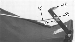
2. Put other end of cover latch rod (A) (end with one bend) in center hole on cover latch bracket (B).
3. Put washer (C) on cover latch rod and fasten with locking ring (D).
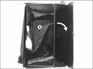
Install Cover
NOTE: Do not install tailgate on MC519 cart when using cover.
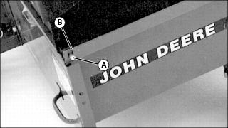
1. Put pivot rod (A) through hole on left-hand corner of cart box flange (B).
2. Pull cover attaching latch (C) outward.
3. Slide pivot rod (A) in slot and release latch.
4. Push cover down so bracket (D) fits over dump cart box flange.
5. Push cover latch bracket (E) rearward to latch cover at rear of cart box.
Install Cover Chute
1. Push cover (A) back and slide clip (B) located on cover chute over front cover support (C) until clip spring snaps in place.
Install Cable and Chain Assembly
IMPORTANT: Avoid damage! To prevent damage to cart, do not operate unit before installing cable and chain assembly. |
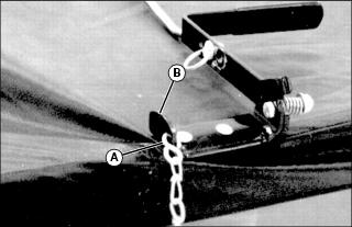
1. Find chain link that is approximately 69 cm (27 in.) from opposite end of cable. Put S-hook (A) through that chain link. Crimp end of S-hook closed.
2. Put other end of S-hook in hole on lift bracket (B), and crimp end of S-hook closed.
Install Chain Bracket On Fender Deck
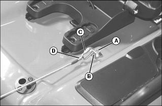
1. Raise seat, and remove bolt (A) and washer from right side of fender deck.
2. Put chain bracket (B) on fender deck and fasten with washer and bolt (removed above). Tighten bolt.
3. Put chain link (C) through loop on end of cable (D) and also through bracket (B). Close chain link and finger tighten nut.
Install Power-Flow Chute
NOTE: Before installing POWER-FLOW chute to MC cart:
• Make sure MC cart is mounted on tractor.
• Make sure cover is installed on cart.
• See POWER-FLOW operator's manual for installing chute to POWER-FLOW.
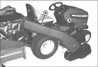
1. Install POWER-FLOW chute (A) in cover chute (B).
2. Install other end of chute to POWER-FLOW. (See your POWER-FLOW operators manual for installation.)