
Installing
Installing Machine Weights and Chains
Use weights to improve stability when operating on slopes or using attachments. |
NOTE: Before attaching blade, remove mower deck from machine. (See Machine Operator’s Manual.)
See your John Deere dealer for weights and chains.
To help traction in difficult conditions it is recommended you:
• Install rear wheel weights on machine.
• Install chains on rear machine tires.
Installing Lift Assembly
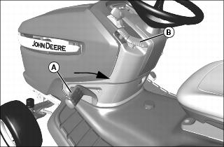
1. Pull lift pedal (A) back by hand to lower attachment to the lower/down position. Pull lock lever (B) up to lock blade in the lowered position.

2. Raise shorter inner lift rod (C) into position, as shown, and install front side of lift rod to bracket (D) of rockshaft. Secure with 10 x 28 mm drilled pin (E) and locking ring.
3. Install rear side of shorter inner lift rod to ear (F) of shaft. Secure with 10 x 28 mm drilled pin (G) and locking ring.

4. Verify that outside rockshaft bracket (H) does not interfere with the mounting plate (I).
• Check in lower/down position, with lift pedal back.
• Check in raised/up position, with lift pedal forward.
• If there is interference, disconnect rear end of inner rod, and rotate yoke to shorten or lengthen rod for proper fit. Install inner lift rod and repeat as necessary
5. Slide blade assembly under machine.
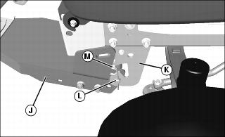
6. Align hole in lift frame (J) with hole in front draft assembly (K), and install front draft pin (L). Secure with 4.5 x 90 mm spring locking pin (M).
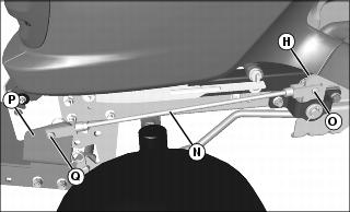
7. Install rear side of longer outer lift rod (N) onto rockshaft bracket (H) with 10 x 28 mm drilled pin (O) and locking ring.
8. Install front side of longer outer lift rod onto lift frame bracket (P) with 10 x 28 mm drilled pin (Q) and locking ring.