
Service Engine
Engine Warranty Maintenance Statement
Maintenance, repair, or replacement of the emission control devices and systems on this engine, which are being done at the customer’s expense, may be performed by any non-road engine repair establishment or individual. Warranty repairs must be performed by an authorized John Deere dealer.
Avoid Fumes
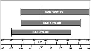
Engine Oil
Use oil viscosity based on the expected air temperature range during the period between oil changes.
The following John Deere oils are preferred:
Other oils may be used if above John Deere oils are not available, provided they meet the following specification:
• API Service Classification CD or higher
Checking Engine Oil Level
1. Park the vehicle safely. (See Parking Safely in the SAFETY section.)
2. Raise and secure cargo box.
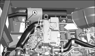
• Remove and wipe dipstick (A) clean.
• Install dipstick. Remove and check oil level.
• Oil level must be between upper and lower fill marks on dipstick.
• If oil level is below lower mark on dipstick, add oil to bring oil level no higher than upper mark on dipstick.
• If oil level is above upper mark, drain to proper level. Determine cause of this condition and correct.
Changing Engine Oil and Filter
IMPORTANT: Avoid damage! Change the oil more often if the vehicle is used in extreme conditions: |
1. Run engine to warm the oil.
2. Park the vehicle safely. (See Parking Safely in the SAFETY section.)
3. Raise and secure cargo box.
4. Place drain pan under engine drain plug.
Picture Note: View from under machine.
5. Remove drain plug (A). Allow oil to drain completely.
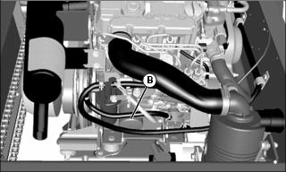
6. Remove and discard oil filter (B) at rear facing side of engine. Wipe off filter base on engine.
7. Put a light coat of clean engine oil on gasket of new oil filter.
8. Install new filter until rubber gasket contacts filter base. Tighten filter an additional one-half turn.
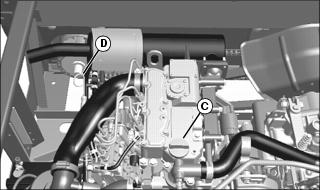
10. Remove oil fill cap (C) from filler opening.
IMPORTANT: Avoid damage! Do not overfill crankcase with oil. Oil capacities given are with engine and crankcase completely dry. Some oil will remain in engine after draining. |
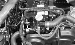
11. Add oil no higher than upper mark on dipstick (D). Do not overfill.
• Capacity with oil filter: 2.2 L (2.3 qt)
12. Install dipstick (D) and oil fill cap (C).
13. Start and run engine at idle to check for leaks. Stop engine. Fix any leaks before operating.
14. Check oil level, add oil if necessary.
Cleaning Rubber Dust Unloading Valve
IMPORTANT: Avoid damage! Do not operate engine without air cleaner element and rubber dust unloading valve installed. |
1. Park the vehicle safely. (See Parking Safely in the SAFETY section.)
2. Raise and secure cargo box.
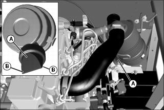
Picture Note: The air cleaner canister cover is removed for clarity only. Removal of the canister cover or dust unloading valve is not required.
3. Locate dust unloading valve (A) attached to the front of the air cleaner canister cover.
NOTE: If canister cover is removed, install with rubber dust unloading valve (A) pointing downward.
4. Visually check dust unloading valve (A). Replace with new valve if worn, damaged, or missing.
5. Pinch corners (B) to allow any dirt or debris to fall out of the valve.
Checking Air Restriction Indicator
1. Park the vehicle safely. (See Parking Safely in the SAFETY section.)
2. Raise and secure cargo box.
NOTE: Indicator will not function correctly if plastic indicator housing is damaged.
3. Locate and check the color at sight window (A) at right rear of machine.
NOTE: You can check function of air restriction indicator by unscrewing indicator from air filter outlet tube and sucking on the indicator’s vacuum port with your mouth. The indicator window should show easy movement of indicator moving into the red zone and should remain there until the reset button (B) is pressed. If not, replace air restriction indicator.
4. If window is clear, no air cleaner service is required.
5. If window is fully red, service air cleaner element(s) immediately. (See Servicing Air Cleaner Element procedure.)
Servicing Air Cleaner Element
1. Park the vehicle safely. (See Parking Safely in the SAFETY section.)
3. Raise and secure cargo box.
4. Release latches (A) and remove air cleaner canister cover (B).
5. Remove and discard primary filter element. Replace with a new filter element.
6. Install air cleaner canister cover with rubber dust unloading valve pointing downward. Check instruction molded into canister cover for proper installation.
7. Hook the canister cover latches.
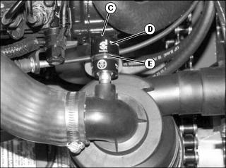
8. Press reset button (C) at end of air restriction indicator (D).
9. Start engine and run at high idle.
10. Shut off engine and wait for all moving parts to stop.
11. Check window (E) on air restriction indicator.
IMPORTANT: Avoid damage! Do not service secondary air filter element unless air restriction indicator window shows red after primary element was replaced. |
12. If air restriction indicator window still shows red, change secondary air filter element:
a. Remove air cleaner canister cover.
b. Remove primary air filter element.
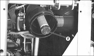
c. Pull secondary air filter element (F) from canister. Discard the filter element.
d. Install new secondary air filter element.
e. Install primary air filter element.
g. Press reset button on air restriction indicator.
Checking Air Intake, Hoses and Clamps
1. Park the vehicle safely. (See Parking Safely in the SAFETY section.)
2. Raise and secure cargo box.
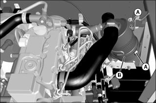
3. Check intake hose (A) for damage or cracking. Replace if necessary.
4. Check and tighten air intake hose clamps (B) (both ends of hose) as needed.
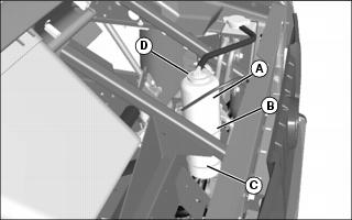
Servicing Sediment Bowl
1. Park the vehicle safely. (See Park Safely in the SAFETY section.)
3. Raise and secure cargo box.
Checking
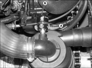
1. Check for water in sediment bowl (A):
• Red ring will float on top of the water.
2. If necessary, clean bowl and replace filter.
Cleaning
1. Close fuel shut-off valve (B).
2. Turn collar (C) to remove bowl (A).
3. Remove filter from inside bowl. Discard filter.
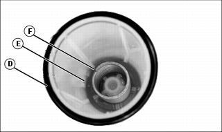
4. Remove and retain O-ring (D), float ring (E), and spring (F) from bowl. Clean bowl and allow drying.
5. Install O-ring, float ring, spring, and new filter into bowl.
6. Install bowl to filter head and tighten collar to secure.
Bleeding Fuel System
DO NOT attempt to service injection pump or fuel injectors yourself. Special training and special tools are required. See your John Deere dealer.
• After you service fuel system.
1. Make sure there is fuel in the tank.
2. Open fuel shut-off valve on filter.
NOTE: If fuel filter has been cleaned or changed, fuel will be heard immediately returning to tank when primer lever is operated. Continue operating lever until you can hear the return flow stop and then start again.
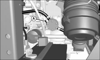
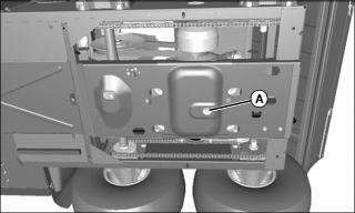
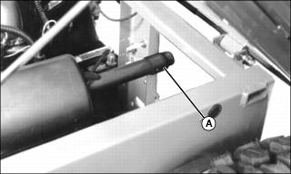
3. Access fuel pump primer lever (A) through opening at rear of vehicle. Move lever up and down. Continue operating lever until:
• Fuel filter bowl is full of fuel.
• You can hear fuel returning to tank through return hose.
Servicing Fuel Injection Pump
IMPORTANT: Avoid damage! Fuel injection pump is calibrated by the engine manufacturer and should not be adjusted. Do not clean a warm fuel injection pump with steam or water. |
Changing injection pump in any way not approved by the manufacturer will end warranty. See your John Deere warranty on this machine.
Do not service injection pump. See your John Deere dealer for service.
If engine is difficult to start, lacks power, or runs rough, check the TROUBLESHOOTING section of this manual. If your engine is still not performing correctly, contact your John Deere dealer.
Cleaning Engine Compartment
1. Park the vehicle safely. (See Parking Safely in the SAFETY section.)
2. Raise and secure cargo box.
IMPORTANT: Avoid damage! Do not spray water on a hot engine or transaxle. Damage may occur to cast aluminum parts. Allow engine to cool before servicing. |
3. Remove any debris in engine compartment.
4. Check and remove any obstructions around the control cables and linkages.
Cleaning Frame Screen and Intake Louvers
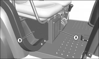
1. Check louvers (A) and screen (B) for dirt, grass clippings and debris.
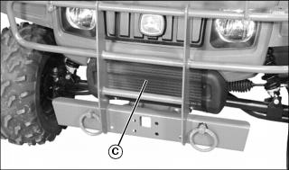
2. Check front radiator screen (C) for dirt, grass clippings and debris.
3. Clean louvers and screen by washing or with a brush or cloth.
Checking Coolant Level
This vehicle has a dual radiator system. One radiator is front-mounted, below the grille. The other radiator is side-mounted under the operator’s seat. There is a single pressure cap, and a single coolant recovery tank at the front of the vehicle, under the hood.
1. Park the vehicle safely. (See Parking Safely in the SAFETY section.)
4. Check coolant level in recovery tank (A):
• If engine is warm, coolant level should be between the FULL line (B) and the LOW line (C).
• If engine is cold, coolant level should be at the LOW line (C) on the recovery tank.
5. Remove recovery tank cap (D) if necessary to add coolant.
6. Add coolant mixture to recovery tank.
Service Cooling System Safely
Servicing Cooling System
Prepare Vehicle
1. Park the vehicle safely. (See Parking Safely in the SAFETY section.)
Draining Cooling System
NOTE: Cooling system capacity without heater kit installed is approximately 8.6 L (9.1 qt), including de-aeration and recovery tanks. Cooling system capacity, with heater kit installed, is approximately 9.7 L (10.3 qt), including de-aeration and recovery tanks.
1. Make sure engine has cooled completely.
2. Raise and secure cargo box.
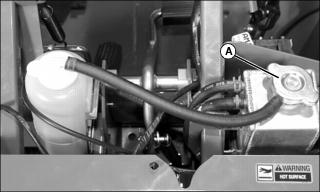
3. Slowly open pressure cap (A) on de-aeration tank to the first stop to release all pressure.
4. Remove cap after all pressure is released.
5. Place a 9.7 L (10.3 qt) drain pan under front radiator.
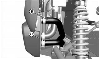
6. Disconnect hoses (B) and (C) at the front radiator, and air bleed hose (D) at thermostat housing on engine. Allow coolant to drain fully from front radiator, then lower hoses (B) and (C) to drain as much coolant as possible from side radiator.
7. Raise rear of vehicle as necessary to allow side radiator coolant to fully drain out to the front.
8. Lower vehicle, and replace hoses (B) and (C). Do not connect air bleed hose (D) at this time.
9. Place a 9.7 L (10.3 qt) drain pan under the engine channel.
10. Remove engine drain fitting:
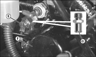
• On machines without heater kit installed, loosen engine block drain (E) near engine oil filter (F). Allow coolant to fully drain into the container.
• On machines with heater kit installed, remove hose from fitting (G) near engine oil filter (F). Allow coolant to fully drain from hose and from engine fitting into the container.
Picture Note: Shown with optional heater kit installed.

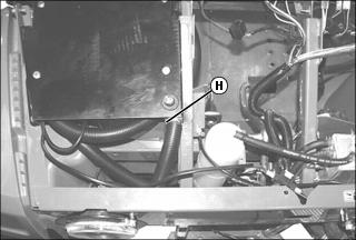
11. On machines with heater kit installed, open heater assembly thumb bleed screw (H) and be sure shut-off valve (I) is in the open position (handle is parallel to centerline of hose).
12. After all coolant has drained, tighten the engine block drain, or if a heater kit is installed, install hose back onto engine fitting and close heater assembly thumb bleed screw.
Flushing Cooling System
2. Prepare a cooling system flushing solution using clean water and John Deere Cooling System Cleaner, John Deere Cooling System Quick Flush, or an equivalent.
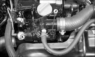
3. Remove screws (J) to remove thermostat housing (K), thermostat, and O-ring. Inspect and replace O-ring if necessary.
4. Fill engine with flushing solution through the thermostat opening. This will save time purging air from the system later.
5. Install O-ring and thermostat housing. Save thermostat, but do not install at this time. Flushing solution should be circulated with thermostat removed. Tighten the thermostat screws to 26 N•m (230 lb-in.).
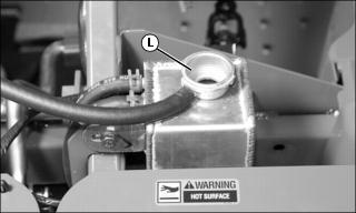
6. Add flushing solution to de-aeration tank (L) until full. Do not install pressure cap at this time.

7. Connect air bleed hose (D) at thermostat housing on engine.
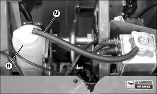
8. Disconnect hose (M) from recovery tank (N) so that flushing solution does not enter the tank.
NOTE: When the thermostat opens the coolant level in the de-aeration tank will fall rapidly and may empty.
10. Monitor flushing solution level and add solution as air is purged from system:
a. When air is purged from system, top off solution level at de-aeration tank, and replace pressure cap.
11. Run engine until it reaches operating temperature.
13. Connect hose (M) to recovery tank (N).
14. Follow instructions for draining and filling cooling system. Thermostat housing will have to be removed, and thermostat installed before filling system after flushing.
Filling Cooling System
NOTE: John Deere COOL-GARD coolant is recommended when adding coolant to the cooling system. Follow the directions on the container for correct mixture ratio.
Cooling system capacity without heater kit installed is approximately 8.6 L (9.1 qt), including de-aeration and recovery tanks. Cooling system capacity, with heater kit installed, is approximately 9.7 L (10.3 qt), including de-aeration and recovery tanks.
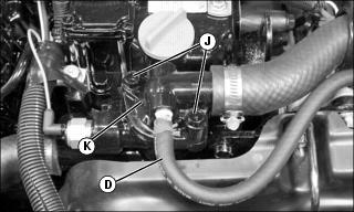
1. Remove screws (J) to remove thermostat housing (K), thermostat, and O-ring. Inspect and replace O-ring if necessary.
2. Fill engine with coolant through the thermostat opening. This will save time purging air from the system later.
3. Install thermostat, O-ring and thermostat housing. Tighten the thermostat screws to 26 N•m (230 lb-in.).
4. If removed, connect air bleed hose (D) at thermostat housing on engine.
5. Add coolant to de-aeration tank (L) until full. Do not install pressure cap at this time.
6. Check coolant level in recovery tank (N), and ensure that level is at or above the low mark. Add coolant if necessary.
• Start engine and run at idle.
NOTE: When engine warms up, the thermostat opens and the coolant level in the de-aeration tank will fall rapidly and may empty.
• Monitor coolant level in de-aeration tank, and add coolant as air is being purged from the system.
• Operate engine at high idle for a few minutes while monitoring fluid in the de-aeration tank for evidence that the thermostat has fully opened. When thermostat fully opens there will be a significant drop (1/3 to 1/2 tank) in the de-aeration tank fluid level. Top off de-aeration tank, replace pressure cap, and run engine an additional 5 to 10 minutes.
• As a final check, stop engine and allow it to cool. Slowly open pressure cap on de-aeration tank to the first stop to release all pressure. Remove cap after all pressure is released, and top off coolant level in de-aeration tank. Replace pressure cap.
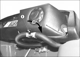
• Turn heater control shut-off valve (I) to the open position (handle is parallel to centerline of hose), and then close valve slightly by turning clockwise (O) 30?.
• Start engine and run at idle.
NOTE: When engine warms up, the thermostat opens and the coolant level in the de-aeration tank will fall rapidly and may empty.
• Monitor coolant level in de-aeration tank, and add coolant as air is being purged from the system.
• Open thumb bleed screw (H) 1 - 2 turns. If coolant comes out, tighten. If sputtering occurs, allow air to escape until sputtering stops and then tighten bleed screw.
• Open heater control shut-off valve fully, so handle is parallel to centerline of hose.
• Operate engine at high idle for a few minutes while monitoring fluid in the de-aeration tank for evidence that the thermostat has fully opened. When thermostat fully opens there will be a significant drop (1/3 to 1/2 tank) in the de-aeration tank fluid level. Top off de-aeration tank, and run engine an additional 5 to 10 minutes.
• When air is purged from system, top off coolant level at de-aeration tank, and replace pressure cap.
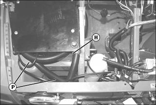
• Check both heater hoses (P). They both should be equally warm to the touch, indicating there isn’t an air block. If only the supply (long) hose is warm, be sure there are no kinks in the hose connected to the rear of the engine, that the control valve is open (handle is parallel to centerline of hose), and that all air has bled from the thumb bleed screw. Be sure thumb screw is tight when complete.
NOTE: The remaining air bubbles in the cooling system will work their way into the de-aeration tank over the next hour of operation.
• After an hour of normal operation, carefully check that the cooling system recovery tank, if coolant is warm, is filled with coolant up to the FULL line. Add coolant to full line, if necessary. If coolant is cool, coolant level should be above the LOW line. As a final check, allow cooling system to fully cool. Once fluid has cooled, check the level of fluid in the de-aeration tank. Top off if necessary.
8. Install hood and lower cargo box.
Recommended Engine Coolant
The following John Deere coolants are preferred:
• COOL-GARD® PRE-DILUTED SUMMER COOLANT (TY16036).
• COOL-GARD® CONCENTRATED SUMMER COOLANT (TY16034).
If neither of the recommended coolants is available, use a glycol base coolant that meets the following specification:
Check container label before using to be sure it has the appropriate specifications for your machine. Use coolant with conditioner or add conditioner to coolant before using.
If using concentrate, mix approximately 50 percent antifreeze with 50 percent distilled or deionized water before adding to cooling system. This mixture will provide freeze protection to -37 degrees C (-34 degrees F).
Certain geographical areas may require lower temperature protection. See the label on your antifreeze container or consult your John Deere dealer to obtain the latest information and recommendations. Never exceed the maximum dilution rate for the coolant you are using. Exceeding the maximum rate will greatly reduce the coolant effectiveness.
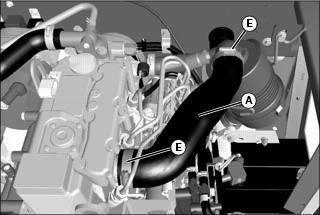
Checking Radiator Hoses and Clamps
1. Park the vehicle safely. (See Parking Safely in the SAFETY section.)
4. Remove service access panel under passenger seat.
NOTE: Visually inspect hoses for cracks and wear. Squeeze hoses to check for deterioration. Hoses should not be hard and brittle, nor soft or swollen.
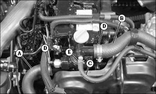
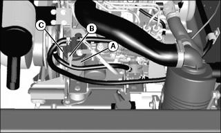
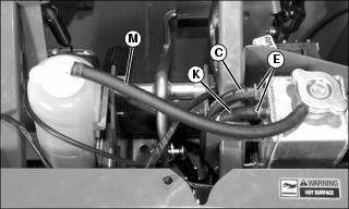
6. Check radiator hoses and air bleed hose connected to the engine for damage or cracking. Replace if necessary.
• Hose (A) goes from engine to intermediate tube.
• Hose (B) goes from engine to side radiator.
• Air bleed hose (C) goes from engine to de-aeration tank.
7. Check hose clamps (D) and (E), and tighten or replace as needed.
NOTE: Removal of service access panel will allow visual inspection of side radiator connections. For most repairs, seat base panel will need to be removed.
Picture Note: Shown with service access panel and seat base panel removed.
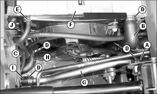
8. Check radiator hoses and air bleed hose at side radiator (F) and intermediate tube (G) for damage or cracking. Replace if necessary.
• Hose (A) comes from engine to intermediate tube.
• Hose (B) comes from engine to side radiator.
• Hose (H) goes from side radiator to front radiator.
• Hose (I) goes from intermediate tube to front radiator.
• Air bleed hose (J) goes from side radiator to de-aeration tank.
9. Check hose clamps (D) and (E), and tighten or replace as needed.
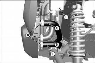
10. Check radiator hoses at front radiator for damage or cracking. Replace if necessary.
• Hose (I) comes from intermediate tube.
• Hose (H) comes from side radiator.
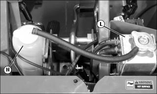
• Air bleed hose (K) goes to de-aeration tank (L).
• Check hose clamps (D), and tighten or replace as needed.
11. Check air bleed hoses (C) and (K), and recovery tank hose (M) for damage or cracking. Replace if necessary.
12. Check hose clamps (E) and replace as necessary.
14. Replace service access panel under passenger seat.
Checking Spark Arrestor
NOTE: Spark arrestor is optional equipment and may not appear on your machine.
1. Park the vehicle safely. (See Park Safely in the SAFETY section.)
2. Allow vehicle to cool completely.
Picture Note: Cargo box shown raised for clarity. Raising cargo box is not necessary.
3. Remove hardware securing spark arrestor (A) to muffler exhaust pipe. Retain the hardware.
5. Make sure deflector screen inside arrestor is not plugged or damaged:
• If plugged, spray with carburetor/choke cleaner and blow dry with low-pressure compressed air.