
Assembly
Prepare Vehicle For Assembly
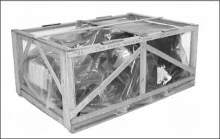
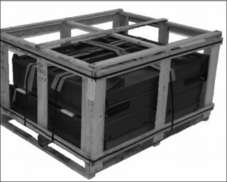
1. Remove top and sides of shipping crate.
2. Locate and identify all parts and hardware.
NOTE: The steel cargo box and front bumper brush guard are in a separate crate.
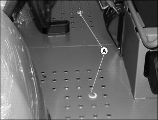
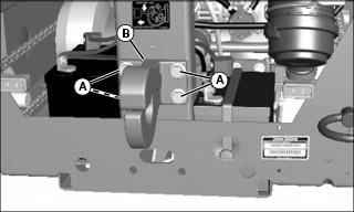
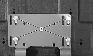
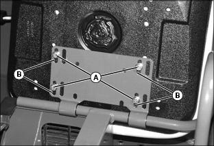
3. Remove front shipping screws and washers (A), on each side of the front platform.
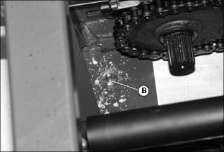
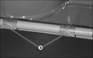
4. Remove two rear-shipping screws and washers (B), on each side of rear frame.
5. Raise vehicle using a safe lifting device. Remove pallet from under vehicle.
6. Position safety stands under vehicle.
Remove Shipping Wrap
2. Remove plastic shipping wrap from hood.
3. Carefully cut the plastic wrap, using a sharp utility knife, where fenders join metal frame.
4. Pull plastic wrap up and away from fender and remove remaining plastic in joint by pulling from below.
5. Remove the plastic wrap from rear fenders and box extensions.
Check Tire Pressure and Condition
1. Keep heavy-duty tires inflated to 41 kPa (6 psi) and Extended Mobility Tires (EMT) tires inflated to 34 kPa (5 psi).
2. Heavy-Duty All Purpose tire inflation pressure can be as low as 27 kPa (4 psi) and EMT tires as low as 14 kPa (2 psi) to provide a better ride.
3. Measure circumference of all tires. Tires with the largest circumference must be placed in the most rearward position to provide the most positive ground contact for drive wheels.
4. Mount wheels with valve stem to outside.
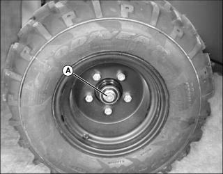
Install Front Wheels and Tires (Heavy Duty)
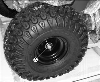
1. Install wheels using M16x40 flange head bolt (A). Tighten to 90 N•m (65 lb-ft).
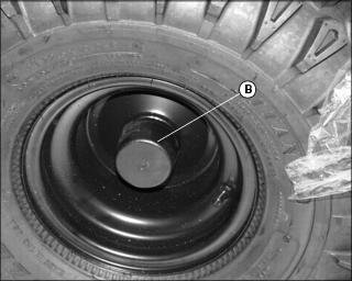
2. Install plastic hubcap (B).
Install Front Extended Mobility Technology Tires (EMT)
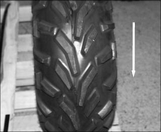
NOTE: Tire treads should be angled as shown below, when viewed from the front of the vehicle. The direction of arrow is forward motion.

1. Install wheel, hub and tire to axle on utility vehicle using one M16x40 flange head bolt (A). Tighten to 90 N•m (65 lb-ft).
2. Install plastic hubcap (B).
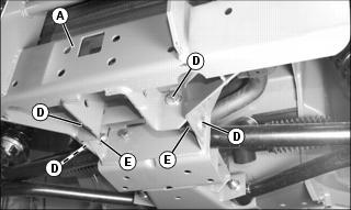
Install Belt and Chain Shield
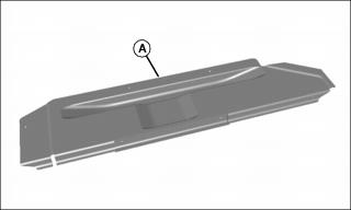
Picture Note: Top view of chain shield.
NOTE: Only one chain shield (A) is used, and is installed on left side of vehicle.
It is easier to install chain shield on frame before left side rear tires and wheels are installed.
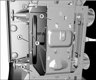
1. From below vehicle, place front lip of chain shield (A) above angle bracket (B) at front left corner of frame opening.
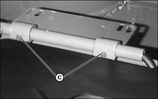
2. Align mounting hole at rear of chain shield with existing hole in frame. Install an M6x20 flange head bolt (C) and M6.6 flat washer through the chain shield and vehicle frame, and secure with an M6.6 flat washer and M6 locknut on the inside. Do not tighten.
3. Secure chain shield to engine channel (D) with three M6x16 tapping screws (E) and M6.6 flat washers, using existing holes. Do not tighten.
4. Secure chain shield to the side frame (F) with two M6x16 tapping screws (E) and M6.6 flat washers, using existing holes. Tighten all hardware.
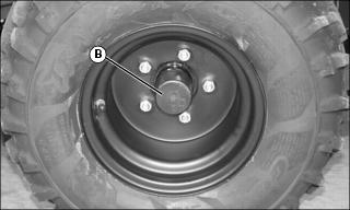
Install Rear Wheels and Tires
NOTE: Only the rear set of wheels and tires should be installed at this time. The middle set of wheels and tires should not be installed until after OPS installation.
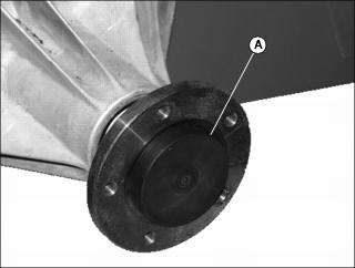
1. Install plastic cap (A) on the rear of each wheel axle shaft hub.
NOTE: If Extended Mobility Technology (EMT) tires are installed, tire treads should be angled as shown below, when viewed from the front of the vehicle. The direction of arrow is forward motion.
2. Attach one wheel and tire to each rear axle using five wheel bolts. Tighten until snug.
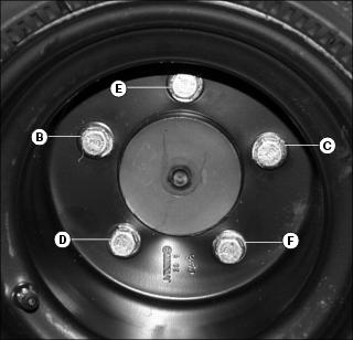
3. Tighten bolts to 90 N•m (65 lb-ft) in sequence (B), (C), (D), (E) and (F).
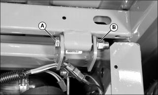
Lubricating Front King Pins
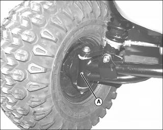
1. Lubricate grease fitting (A) on each king pin bushing with one or two shots of recommended grease.
2. Wipe off excess grease from fitting.
Install Steering Wheel
1. Remove and discard plastic protective cap from steering shaft.
2. Install steering wheel onto steering shaft. Turn steering wheel to position front wheels straight and facing forward.
4. Apply multi-purpose grease to steering shaft.
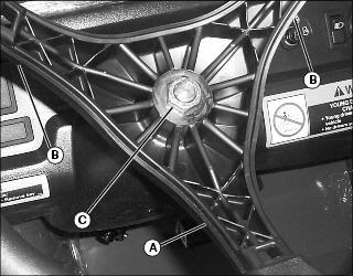
5. Install steering wheel onto steering shaft with one spindle (A) positioned at 180? at bottom of wheel and spindles (B) at approximately 45? at top of wheel.
6. Position front wheels straight and facing forward.
7. Install steering wheel onto steering shaft.
8. Install and tighten nut (C) to 38 N•m (28 lb-ft).
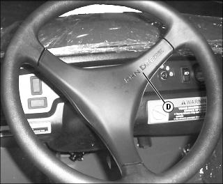
9. Install cover (D) so the John Deere name is positioned properly.
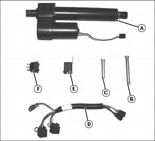
Install Power Lift Kit
Parts in Kit
Install Kit
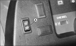
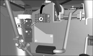
2. Push out dash plug and install the lift switch (A).
NOTE: Hold switch in place when connecting connector to avoid switch from popping out of dash.
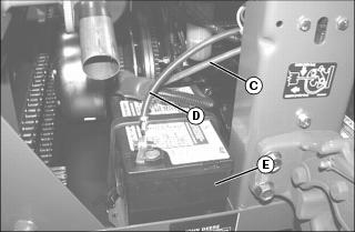
3. Plug connector (B), from main wiring harness, to switch (A).
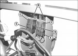
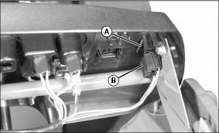
4. Install relays (C) to inside of rear frame with two bolts (D) and nuts. Nuts go to inside of frame.
5. Connect relay wiring harness connectors (E) to relays (C), either connector to either relay.
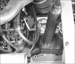
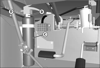
6. Remove left battery (F), to gain access to frame mounting brackets.
7. Position lift cylinder (G) with motor facing to rear, and lower mounting hole aligned with frame mounting brackets. Install short drilled pin (H), through brackets and lift cylinder, and secure on other side with M13 flat washer and spring locking pin.
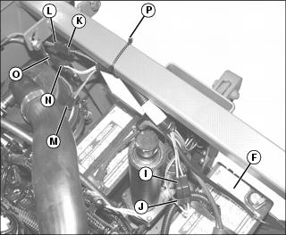
8. Plug wire connector (I), from lift motor, into the relay wiring harness connector (J) (orange and purple wires).
9. Plug connector (K) (red / black wires, female connector) on relay harness, to connector (L) (red / black wires) on main harness. An additional connector (M), with red / black wires (male plug), is supplied on relay wiring harness for auxiliary switched power to an additional attachment.
10. Plug connector (N) (orange / green wires) into connector (O) (orange / green wires) on main harness.
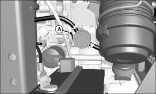
11. Secure wiring to rear of frame near air cleaner with tie strap (P).
13. Upper lift cylinder mount will be secured to cargo box with long drilled pin and spring locking pin.
Check Battery Voltage
Remove and discard the protective caps from the positive (+) and negative (-) terminals.
Battery is filled with acid and charged when it left the factory. To extend battery life, check voltage prior to delivery. Fully charge the battery if voltage is less than 12.6 volts.
Install Battery Wiring
IMPORTANT: Avoid damage! Route positive (+) and negative (-) cables to avoid contact with battery posts or other objects where rubbing could cause cable damage. |
1. Locate the two loose battery cables from the bag of parts; one black ground cable, one red positive cable with two red terminal boots, and hardware.
NOTE: Make sure that ignition switch and all other electrical switches are in the STOP or off position before installing battery wiring.
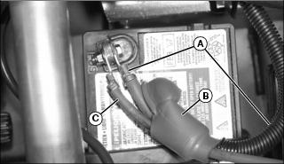
2. Remove and discard existing red terminal boot from the positive battery cable (A) on the vehicle harness. Insert the now uncovered end of cable (A) into the back of the round boot (B).
NOTE: The two positive (+) cables, (A) and (C), should not cross over each other within the terminal boot, to avoid chafing and wear to cable insulation.
3. Connect the two cables in the boot to the positive (+) terminal of the left side battery, with cable (A) at the right side of the terminal, and the second cable (C) at the left side of the terminal. Position the two cables so that they are laying flat on the battery, secure with supplied terminal hardware, and cover terminal with boot (B).
4. Connect one end of black ground cable (D), from bag of parts, to negative (-) terminal on left side battery (E). Secure with supplied terminal hardware.
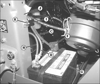
5. Loop positive cable (C) from the left side battery, behind the lift cylinder, and across to the positive (+) terminal of the right side battery. Secure cable with supplied terminal hardware, and cover terminal with square boot (F).
6. Loop ground cable (D) over to negative (-) terminal on right side battery (G).
7. Locate loose end of black primary ground cable (H). Connect loose ends of ground cables (D) and (H) to negative (-) terminal on right battery, one on each side of terminal. Secure with supplied terminal hardware.
8. Install cable clamp (I) around cables (C) and (D), making sure that positive cable (C) is to the front in the clamp, and negative cable (D) is to the rear in the clamp. Secure clamp to existing hole at right side of center support (J) with an M6x20 flange head bolt (K) and locknut.
Picture Note: Battery cable routing, overall view.
9. Double-check all cable connections, cable routing, and ensure that terminal covers are in position over positive (+) battery terminals.
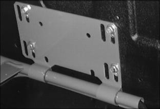
Install Pintle Hitch
1. Install four M12x35 flange head bolts (A) through the hitch plate (B) and vehicle frame, and secure on the inside with four M12 locknuts.
2. Tighten hardware to 132 N•m (97 lb-ft).
Install Bumper and Brush Guard
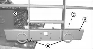
1. Secure front bumper / brush guard (A) in a large vise, and install lift and tie-down rings (B) in the existing holes in the front bumper. Secure from the inside with 3/4 in. nuts (C).
2. Hold ring with wooden or plastic bar to prevent rotation of the ring during tightening of each nut.
NOTE: The ring must be free to rotate. If it does not, loosen the nut until it does.
3. Tighten each 3/4 in. nut (C) until it just contacts the shoulder on the tie-down ring bolt.
NOTE: If installing litter carrier, do not tighten bumper / brush guard mounting hardware at this time. Leave hardware loose.
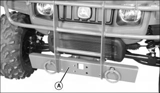
4. Secure front bumper / brush guard (A) to utility vehicle frame with four M12x25 carriage bolts (D), installed from the outside, and four locknuts (E), on the inside. Tighten locknuts to 132 N•m (97 lb-ft).
Install Seats
NOTE: If installing an occupant protective structure (OPS), install seats after OPS is installed.
1. Remove flange head bolts (A) from bottom of seat base bracket on each seat.
NOTE: Apply silicone lubricant to inner surface of seat bushings to improve ease of seat rotation if desired.
2. Install seat bushings (B) onto support rail so tabs face toward rear of vehicle.
3. Position seat base bracket onto support rail so hinges (C) fit around plastic bushing tabs.
NOTE: Install seat hardware in the correct slots in the bracket. Always use set of slots closest to center of vehicle when installing seat.
4. Rotate seat bracket upward. Install original hardware in slots closest to center of vehicle to secure seat. Do not tighten completely.
Adjust Seats
Picture Note: Passenger seat shown.
1. Loosen four flange head bolts (A).
2. Move seat forward or rearward in slots (B) to position desired.
3. Tighten bolts 10 N•m (7 lb-ft).
Install Cargo Box
1. Safely remove cargo box from crate.
NOTE: A hoist may be necessary to lift and align cargo box on to frame.
2. Place cargo box onto frame; align hinge tabs on rear of frame and bushings on cargo box.
3. Attach box at rear on each side using M12x90 hex head bolts (A) and flanged lock nuts (B). Install bolts with threads to the outside of vehicle.
NOTE: It may be necessary to tighten bolts to squeeze tabs to minimize noise from vibration. Use spray lube to eliminate squeaks until pivot points wear in.
4. Tighten bolts, pulling in tabs until they contact ends of bushings.
5. Spray bushings and tab area with a spray lubricant.
6. Lift cargo box by hand and safely prop box open for lift cylinder access.
7. Turn ignition switch to run position ONLY. Press RAISE position on switch to extend cylinder.
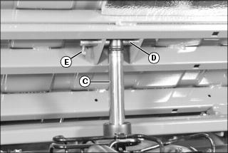
8. Fasten lift cylinder (C) to cargo box with long drilled pin (D) and spring pin (E) from the Lift Cylinder Kit.
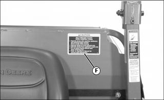
9. Apply decal (F) on front left side of load guard as shown:
• Remove backing, use squeegee to carefully smooth decal on load guard to avoid air bubbles and wrinkles. If air bubbles occur, pick with a pin and smooth out.
• Decal MUST be fully displayed and NOT obstructed by operator’s seat.
Install Fire Extinguisher
1. Remove fire extinguisher from bracket (A).
2. Position fire extinguisher bracket so that the left outer two holes are aligned with the clip nuts on the mounting bracket, and secure with two M6x20 flange head bolts (B).
3. Place the fire extinguisher (C) into the bracket, so that the bracket tongues (D) fit into the grooves of the extinguisher head.
4. Close clamp around extinguisher body.
Check Fluid Levels
NOTE: Refer to the Service sections of the operator’s manual for information concerning check locations and proper fluid levels.
1. Check radiator coolant level.
Prepare Fuel System
NOTE: See OPERATING section of the operator’s manual for information concerning fuel shut-off valve.
1. Add diesel fuel to fuel tank.
2. If required, open fuel shut-off valve.
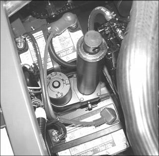
3. If required, access fuel pump primer lever (A) through opening at rear of vehicle. Move lever up and down. Continue operating lever until:
• Sediment bowl of fuel filter is full of fuel.
• You can hear fuel returning to tank through return hose.
Clean and Polish Plastic Hood and Fenders
1. Remove any dust or dirt with water.
2. Dry thoroughly to avoid water spots.
3. Spray PLEDGE®1 onto plastic surfaces and leave on for 30 to 60 seconds.