
Operating
Daily Operating Checklist
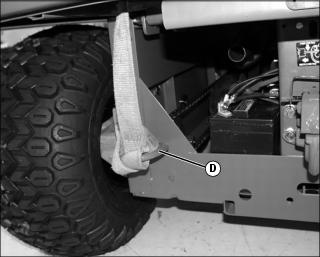
o Remove debris from engine compartment, especially around brake linkage on each side of the transaxle.
o Check to make sure air intake is clean.
o Check area below machine for leaks.
o Check brakes and park brake operation.
Avoid Damage to Plastic and Painted Surfaces
• Do not wipe plastic parts unless rinsed first.
• Insect repellent spray may damage plastic and painted surfaces. Do not spray insect repellent near machine.
• Be careful not to spill fuel on machine. Fuel may damage surface. Wipe up spilled fuel immediately.
Using Hand Holds
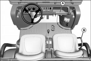
Hand holds are provided for passenger balance. When a passenger is present, they shall use both of the hand holds at all times while the machine is moving: the dash bar (A), and the side rail (B) to the right of the seat.
Adjusting Standard Seat
NOTE: If seat is removed, install seat hardware in the correct slots in the bracket. Always use set of slots closest to center of vehicle when installing seat.

Picture Note: Passenger seat shown.
2. Hold onto seat and loosen cap screws (A).
3. Slide seat forward or rearward for desired position.
4. Tighten seat cap screws to 10 N•m (7 lb-ft).
Testing Safety Systems
The safety systems installed on your machine should be checked before each machine use. Be sure you have read the machine operator manual and are completely familiar with the operation of the machine before performing these safety system checks.
Use the following checkout procedures to check for normal operation of machine.
If there is a malfunction during one of these procedures, do not operate machine. See your authorized dealer for service.
Perform these tests in a clear open area. Keep bystanders away.
Testing the Safety Start System
1. Sit on the operator’s seat.
2. Turn ignition switch to STOP position.
4. Move gear shift lever to forward position.
5. Move ignition switch to start position. Engine should not crank. Turn ignition switch to STOP position.
6. Move gear shift lever to reverse position.
7. Move ignition switch to start position. Engine should not crank. Turn ignition switch to STOP position.
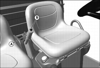
Using the Seat Belts
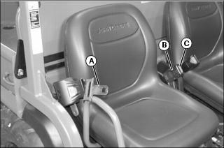
Fasten Belt
1. Grasp outer seat belt connector (A), pull out and across body to inner connector (B), at inside of seat.
2. Push outer connector firmly into inner connector until it locks.
Release Belt
1. Press red button (C) on inner connector to release seat belt.
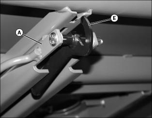
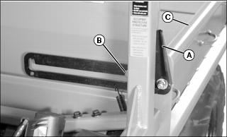
Raising and Lowering Occupant Protective Structure (OPS)
Lowering OPS Crossbar
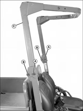
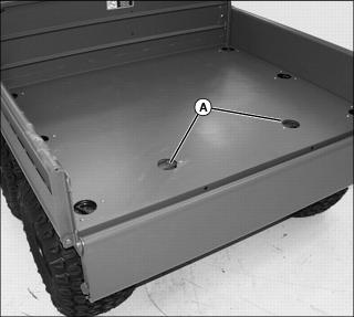
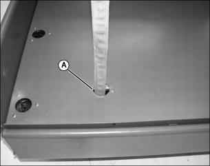
1. Remove 1/2-13 x 3-1/4 in. flange head bolt and locknut from front position (A) at each OPS bracket.
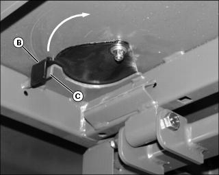
2. Loosen the 1/2-13 x 3-1/4 in. hardware at the rear (pivot) position (B) at each OPS bracket, and lower OPS crossbar (C) to rest on cargo box deck.
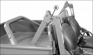
3. If OPS is lowered for transport, tighten pivot hardware at position (B), and store removed hardware for later use.
Raising OPS Crossbar
1. Loosen pivot hardware at (B) if necessary, and raise OPS to upright position.
2. Insert 1/2-13 x 3-1/4 in. flange head bolts, removed earlier, through OPS crossbar and upright brackets, from the outside, and secure at the inside with 1/2 in. locknuts.
3. Tighten all hardware to 115 N•m (85 lb-ft).
Using Park Brake
Always lock the park brake and remove the key before leaving the machine unattended. |
Locking the Park Brake:
1. Push down on brake pedal to hold machine in place.
2. Pull up on lever (A) and lock lever into position engaging park brake.
Unlocking the Park Brake:
1. Push down on brake pedal to hold machine in place.
4. Release lever down completely.
Using Ignition Switch
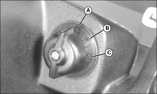
A - STOP Position - With ignition switch in STOP position, all switched power is off, and engine should not run.
B - Run Position - Turn ignition switch from STOP to this position and all switched power circuits will be on.
C - Start Position - Turn ignition switch to start position to crank the engine. Release switch after engine has started and it will automatically return to the run position. The engine will continue to run.
Using Headlights
Ignition switch/Key must be in the run position to operate the lights. If the Ignition switch/key is in the run position and the engine is not running, the battery will discharge if the lights are allowed to remain on for an extended period of time.
• Press top of light switch to turn headlights on.
NOTE: Be sure to turn lights off and turn the ignition switch/key to STOP position, or lights will discharge battery.
• Press bottom of light switch to turn headlights off.
Using Deluxe Garrison Lights (Optional)
The deluxe garrison lights are controlled with a 3-position switch as follows:
• Up - Headlights, tail lights, front marker lights, and beacon light will be on. Turn signals, hazard lights, and reverse lights will be enabled.
• Middle - Tail lights, front marker lights, and beacon light will be on. Turn signals, hazard lights, and reverse lights will be enabled.
• Down - All lights will be off. (Blackout lights still function.)
Using Turn Signal Switch
NOTE: Turn signals will only operate when head light switch is in the ON position.
• Press at left end of turn signal switch to signal a left turn.
• Press at right end of turn signal switch to signal a right turn.
• Press at opposite end of turn signal switch until switch is centered to turn signal light off.
Using Hazard Lights
NOTE: Hazard lights will only operate when head light switch is in the ON position.
• Press at top of hazard light switch to turn hazard lights on.
• Press at bottom of hazard light switch to turn hazard lights off.
• Hazard lights override the turn signal function. To operate turn signal, turn off hazard lights.
Using Black Out Lights (Optional)
Ignition switch must be in the run position to operate the Black Out lights. If the ignition switch is in the run position and the engine is not running, the battery will discharge if the lights are allowed to remain on for an extended period of time.
• Press top of light switch to turn Black Out headlight and marker lights on.
NOTE: Be sure to turn lights off and turn the ignition switch to STOP position, or lights will discharge battery.
• Press bottom of light switch to turn all Black Out lights off.
Using and Checking Instrument Panel
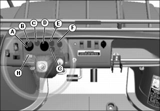
A - Voltmeter (Optional) - This gauge indicates system voltage. Indicator should be near center position while engine is running. If indicator is in either low or high (red) positions, stop engine and go through diagnostic procedures to repair problem.
B - Battery Discharge Light - This light will illuminate when the ignition switch is in the run position and the engine is not running. If this light illuminates when the engine is running, see your John Deere dealer.
C - Engine Coolant Temp / Glow Plug Light - This light will illuminate when the ignition switch is placed in the run position and the engine/glow plugs are cold. After approximately 3 - 5 seconds, the light will turn off. Additionally, this light will illuminate when the engine coolant is approaching a dangerously hot temperature. If this light illuminates during operation, remove load on machine immediately. Reduce engine to idle speed and check for something blocking air flow to the radiator and check engine coolant level. If light stays on, stop engine.
D - Speedometer (Optional) - The speedometer indicates machine speed in Km/hr (mph).
E - Park Brake Light - This light will illuminate when the ignition switch is in the run position and the park brake is locked.
F - Traction Assist (Differential Lock) Light - The traction assist light will illuminate when the traction assist lever is engaged and the differential lock system is engaged within the transaxle. Traction assist light will go out when lever is disengaged, and the differential lock system within the transaxle is disengaged.
G - Engine Oil Pressure Light - This light will illuminate when the ignition switch is in the run position and the engine is not running. If this light illuminates while the engine is running, engine oil pressure is too low. Stop engine.
IMPORTANT: Avoid damage! Hour meter will accumulate hours when the ignition/key switch is in the Run position. Turn key to STOP to avoid a false hour meter reading. |
H - Hour Meter - The hour meter operates and displays when the engine is running. The hour meter shows the accumulated number of hours the engine has run. The hour meter is intended to provide a means of monitoring machine usage for maintenance purposes. Use the hour meter to determine when your machine has reached the recommended service intervals.
Using Accessory Outlet
NOTE: Accessory must be rated at 10 amps or less.
The accessory plug does not turn off with the key switch. Items connected to the accessory plug will continue to draw power, draining the battery.
• Remove 12-volt outlet cover and install accessory cord in outlet.
• Install cover in outlet after use.
Using Steering Wheel Lock Cable
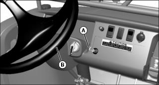
1. Pull looped end of steering wheel lock cable (A) out from storage position in dash.
2. Wrap cable around the top of the steering wheel (B) and pinch loop at end of cable to the main cable just under the steering wheel. Secure cable loop to main cable with a padlock.
Starting the Engine
1. Sit on operator seat. Do not start engine at this time.
2. Push down on accelerator pedal to check free movement of pedal assembly. Release pedal.
NOTE: The machine has a neutral start safety switch. The engine will not start unless the transaxle shift lever is in N (Neutral) position.
3. Verify that transaxle shift lever is in N (Neutral) position.
4. Verify that park brake is locked.
5. Turn ignition/key switch to the Run position.
6. Check that the following indicator lights are on.
• glow plug/coolant temperature light for approximately 3 - 5 seconds
7. When the glow plug/coolant temperature light turns off, turn ignition/key switch to START position.
IMPORTANT: Avoid damage! Starter may be damaged if operated continuously for extended periods of time. Allow starter to cool down after several starting attempts. |
8. Release ignition/key switchto the Run position when engine starts.
• If engine does not start within five seconds, turn ignition/key switch to STOP position and wait ten seconds before trying to start again.
• Attempt starting engine five times only, then wait 5 minutes before trying again. This will allow time for starter to cool and prevent damage to starter.
IMPORTANT: Avoid damage! Do not operate the engine at full throttle or under load until engine has warmed up, or engine damage could occur. |
9. Run engine at half speed for 2 or 3 minutes to warm the engine.
Stopping Engine
Always lock the park brake and remove the key before leaving the machine unattended. |
IMPORTANT: Avoid damage! Do not stop engine immediately after hard or extended operation. Keep engine running at low idle for about 2 minutes to prevent heat build-up. |
2. Move transaxle shift lever to N (Neutral) position.
4. Turn ignition/key switch to STOP position.
5. Remove key (if key operated).
Using Travel Controls
1. Push down brake to stop vehicle.
2. Allow engine to come to a low idle speed.
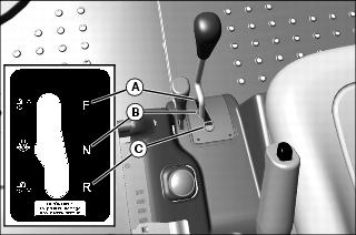
• Forward - Push shift lever to right, then push forward to (A) gear.
• Neutral - Push shift lever to right then to center (neutral) position (B).
• Reverse - Push shift lever to right, then pull rearward to reverse (C) gear.
4. Use the traction assist as needed.
5. Look in the direction the vehicle will travel.

6. Push down accelerator pedal (D) slowly and smoothly to begin vehicle travel.
7. Release accelerator and apply brake pedal (E) evenly and firmly to slow down or stop.
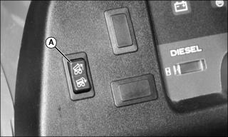
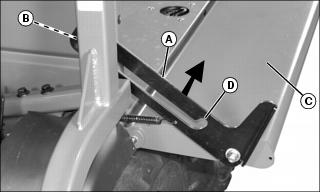
Using Traction Assist (Differential Lock)
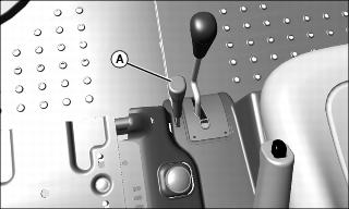
Traction assist (A) is a differential lock system which provides better traction to the rear wheels when needed. Engaging the traction assist will cause both rear wheels to turn together at equal speed.
The traction assist light will turn on when the traction assist lever is engaged and the differential lock system within the transaxle is engaged. Traction assist light will go out when lever is disengaged, and the differential lock system within the transaxle is disengaged.
Engaging the Traction Assist:
1. Stop or reduce engine speed to 1/3 throttle or less.
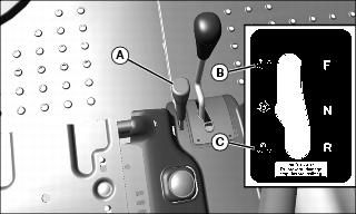
2. Push traction assist lever (A) forward to locked position (B):
• Traction assist will remain engaged as long as lever is forward.
Disengaging the Traction Assist
1. Pull lever rearward to unlocked position (C).
2. Drive the vehicle straight ahead at a constant speed.
3. Reduce engine speed to 1/3 throttle or less.
Raising and Lowering Cargo Box Using Power Lift
1. Park the vehicle safely. (See Parking Safely in the SAFETY section.)
2. Turn ignition switch to run position.
3. Raise and secure cargo box by pressing and holding top of rocker switch (A). Release switch when box is at desired dump height or when reaching maximum height.
NOTE: Allowing the Power Lift actuator clutch to slip briefly (click or ratchet) after cargo box is fully lowered will help keep cargo box secure and reduce rattling caused by travel vibrations.
4. Completely lower cargo box by pressing and holding bottom of rocker switch.
5. Turn ignition switch to STOP position.
Transporting Litters or Stretchers on Cargo Box or Front Carrier (Emergency Use Only)
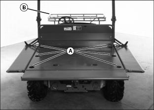
• Lower the cargo box side panels and securely anchor the litters or stretchers to the to the cargo box using the tie-down rings (A). Refer to instructions provided by the litter or stretcher manufacturer to properly secure the patient to the litter or stretcher and to anchor the litter or stretcher to the cargo box bed.
• If the cargo box is utilized completely, place litter or stretcher in the front carrier. Refer to instructions provided by the litter or stretcher manufacturer to properly secure the patient to the litter or stretcher and to anchor the litter or stretcher to the front carrier.
• Regulate speed, especially over rough terrain, to minimize shock and vibration levels experienced by patients being transported.
• Avoid any objects that could contact patients during transport.
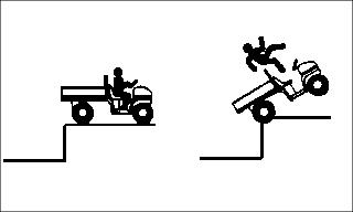
• Avoid holes, slopes or sidehills that may result in a rollover. Transporting cargo can affect the vehicle operation and handling.
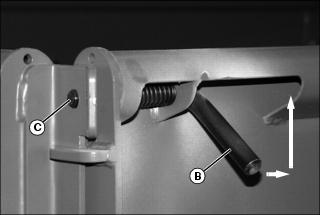
Operating the Tailgate
Lower Tailgate Using Tailgate Support
NOTE: Use the tailgate support to carry a longer load with tailgate down.
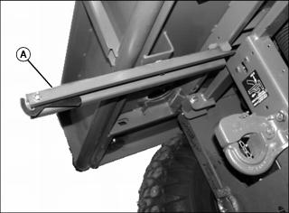
1. Pull tailgate support arm (A) out from under cargo box.

2. Pull latch rod handles (B) up and towards center of tailgate at the same time to release tailgate latches from holes (C) in side panel.
3. Lower tailgate (D) until resting on tailgate support arm. Latch hook/arm into tailgate.
4. Pull up tailgate to close and snap latch rods back into side panel holes at the same time.
5. Push tailgate support arm back under cargo box.
6. Push rod handles down to avoid snagging on clothing.
Latching the Tailgate to the Tailgate Support Arm
NOTE: The support arm has a latch handle (E) that will hold the lowered tailgate firmly to the support arm (A).
1. Pull the tailgate support arm (A) out from under the cargo box.
2. Lower tailgate to support arm.
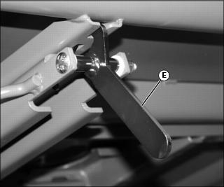
3. Pull up on the latch handle (E) until it connects into slot of support arm.
4. To release tailgate, push in on handle (E) and return support arm to the stored position under the cargo box.
5. Close cargo box and be sure the latch rods snap securely into the holes in the side panels.
Lower Tailgate Without Tailgate Support
1. Pull latch rod handles (B) up and towards center of tailgate at the same time to release tailgate latches from holes (C) in side panel.
3. Pull up tailgate to close and snap latch rod handles back into holes at the same time.
4. Push rod handles down to avoid snagging on clothing.
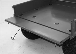
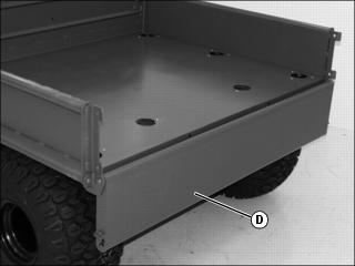
Lowering Cargo Box Side Panels
1. Lower the tailgate onto the tailgate support arm.
2. Pull outward on latch handle (A) at the front of cargo box to lift and disengage latch from pin (B), and pull on the side panel (C) to lower.
3. To raise side panel, pull up on latch near middle (A) to lift and disengage latch from pin (B). Raise panel (C) until the lower detent (D) in the latch engages latch pin (B).
4. Pull up tailgate to close and snap latch rods back into holes at the same time.
5. Push rod handles down to avoid snagging on clothing.
6. Pivot tailgate support arm to storage position.
Using Cargo Box Tie-Down Rings
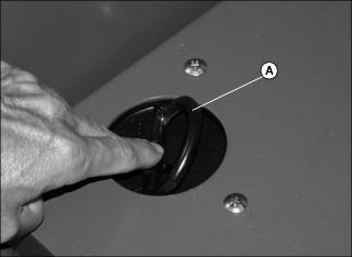
1. Place your finger on the flat of the tie-down ring and push to access the ring loop (A).
IMPORTANT: Avoid damage! To avoid damage to side panels and tailgate, place bulk of load over the main cargo box area. Do not overload tailgate or side panels. |
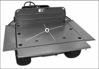
2. Arrange load so that the weight is centered over the main cargo area (B).
3. Secure loads to the tie-down rings in a safe and secure manner.
Using Sling Load Portal® Rings
NOTE: The Sling Load Portals (A) located to the rear of the cargo box allow access to the rear lift rings.
NOTE: There is a gap between the tab (B) and the frame stop (C). If necessary pry open the Sling Load Portal in the case of a tight condition.
1. Reach under edge of cargo box to the tab (B) of the Sling Load Portal and swing open.
2. Place an approved lifting device through the Sling Load Portal (A) in the cargo box.
NOTE: Rings on the four corners of the vehicle are for lifting or tiedown. Rings (D) must be free to rotate.
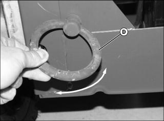
3. If not free to rotate, loosen nut until the rings (D) are free.
4. Secure the lifting device to the lifting ring (D).
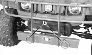
5. There are two lifting rings (E) on the front of the vehicle also.
Using Pintle Hitch
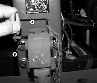
1. Remove wire lock (A) from lock pin (B) and remove lock pin.
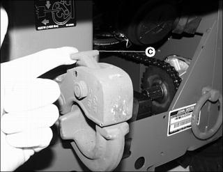
2. Pull the hitch lock (C) forward.
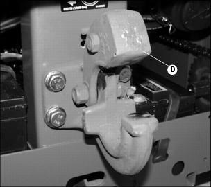
4. To lock hitch, install lock pin and wire lock.
Loading Cargo Box
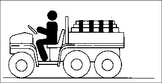
Maximum payload capacity on level terrain for the cargo box for the M-GATOR is 450 kg (1000 lb).
Reduce load and ground speed when operating over rough or hilly terrain. Do not overload vehicle. Limit loads to those that can be safely controlled.
Securely anchor and evenly distribute loads in cargo box, when loading objects into vehicle. Shifting loads will affect stability.
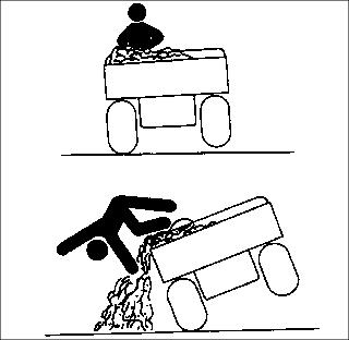
Avoid concentrated loads at rear or side of cargo box to prevent vehicle from tipping over. Be sure load is evenly distributed.
Because there is a big difference in weight between dry and wet sand, the only way of getting true weight of the load you are carrying is by using a weigh scale.
For example, dry sand weighing 450 kg (1000 lb) would be approximately 3/4 of cargo box volume for the M-GATOR..
Printed weight is normally on bagged and other material.
Emptying Cargo Box
1. Back up vehicle to dump site.
2. Park the vehicle safely. (See Parking Safely in the SAFETY section.)
NOTE: If power lift system will not lift load, lower cargo box completely and remove excess load by hand before dumping.
4. Raise and secure cargo box to dump load.
5. Lower cargo box when empty.
6. Latch tailgate closed. Do not drive vehicle with cargo box in raised position.
Towing Loads
• To provide adequate braking ability and traction, weight of towed load (trailer + cargo) must never exceed the vehicle payload (operator + passenger + cargo box load).
• DO NOT tow a load that exceeds 635 kg (1400 lb):
• DO NOT exceed a tongue weight of 45 kg (100 lb).
• Never exceed 16 km/h (10 mph) when towing a load. Tow load at a speed slow enough to maintain control.
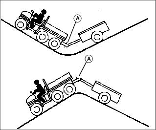
• Always use approved hitch and hitch point provided for the utility vehicle. DO NOT modify the hitch or hitch point in any way.
Using Correct Tires and Inflation
Tires
Use of John Deere approved original equipment or optional equipment is recommended. To ensure maximum machine performance and ride quality, do not mix size, type, or placement of tires. Failure to place tires per the guidelines could result in reduced machine performance, diminished traction and poor handling.
Heavy Duty All Purpose (HDAP)
• 22.5x10⁻⁸ tires installed on front.
• 25x13-9 tires installed on rear.
Run-Flat - EMT (Extended Mobility Tire)
• 22x11-10 tires installed on front.
• 25x11-10 tires installed on rear.
Inflation
IMPORTANT: Avoid damage! Over inflation may damage tires and diminish ride quality. Under inflation could cause wheel damage when riding over rough terrain. |
An accurate low pressure gauge is available at your John Deere dealer.
2. Check tire pressure with an accurate gauge.
3. Add or remove air, if necessary.
Tire Chains
IMPORTANT: Avoid damage! Loose tire chains can cause machine damage. Periodically check chain tightness and adjust as necessary. |
NOTE: For TH 6x4 and M-Gator models, chains are available for rearmost wheels only.
Chains are available for rear wheels only from your John Deere dealer.
Transporting Vehicle
NOTE: Space limitations may vary from one truck manufacturer to another. Short bed trucks do not have the necessary length requirement to accommodate the machine.
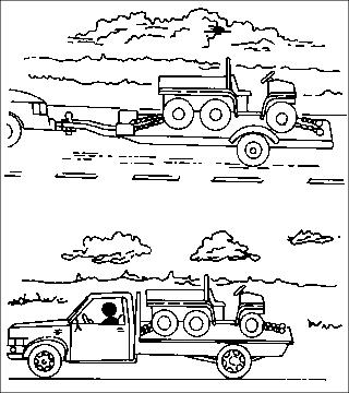
1. Back utility vehicle onto the trailer or truck.
2. Leave gear shift lever in forward or reverse gear.
3. Park vehicle safely. (See Parking Safely in the SAFETY section.)
4. Fasten vehicle to trailer or truck with straps, chains, or cables.
5. Equip the trailer or truck with all the necessary lights and signs required by local, state, provincial, or federal laws.