
Using a High Capacity Alternator
NOTE: See your authorized dealer for purchase of a high capacity alternator kit.
If your vehicle is equipped with accessories that place a higher demand on the charging system, the vehicle’s charging system may be supplemented with the use of a high capacity alternator kit as follows:
Unless use cycles are extremely short and intermittent, a high capacity alternator is recommended with any of the following options:
Unless use cycles are short and intermittent, a high capacity alternator is recommended with any of the following options:
Unless use cycles are short and intermittent, a high capacity alternator is recommended with the use of two or more of the following options:
Service the Battery Safely

Checking the Battery (Sealed Batteries)
NOTE: Do not attempt to open, add fluid or service battery. Any attempt to do so will void warranty.
• Keep battery and terminals clean.
IMPORTANT: Avoid damage! This battery comes fully charged. If the machine is not used by the service expiration date indicated on the battery, charge the battery. |
• Recharge, if necessary, at 6-10 amperes for 1 hour.
Removing and Installing Battery
Removing
1. Park the vehicle safely. (See Parking Safely in the SAFETY section.)

3. Disconnect all black negative cables (A) from battery first.
4. Slide back rubber protective cover (B) and disconnect all red positive cables.
5. Loosen hardware (C) that secures battery hold-down (D) and pivot hold-down away from battery.
Installing
1. Install battery into vehicle with negative (-) terminal positioned toward front of vehicle and the battery seated properly in the battery tray.
2. Pivot battery hold-down firmly against battery and tighten retaining hardware to secure.
3. Connect all red positive cables to positive (+) battery terminal first. Tighten the connections.
4. Connect all black negative cables to negative (-) battery terminal. Tighten the connections.
5. Apply general purpose grease or silicone spray to battery terminals to help prevent corrosion.
6. Slide protective cover down the battery positive cable and seat it over the positive (+) terminal.
Cleaning Battery and Terminals
1. Park machine safely. (See Parking Safely in the SAFETY section.)
2. Disconnect and remove battery.
3. Wash battery with solution of four tablespoons of baking soda to one gallon of water. Be careful not to get the soda solution into the cells.
4. Rinse the battery with plain water and dry.
5. Clean terminals and battery cable ends with wire brush until bright.
7. Attach cables to battery terminals using washers and nuts.
8. Apply spray lubricant to terminal to prevent corrosion.
Using Booster Battery
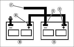
1. Connect positive (+) booster cable to booster battery (A) positive (+) post (C).
2. Connect the other end of positive (+) booster cable to the disabled vehicle battery (B) positive (+) post (D).
3. Connect negative (–) booster cable to booster battery negative (–) post (E).
4. Connect the other end (F) of negative (–) booster cable to a metal part of the disabled machine engine block away from battery.
5. Start the engine of the disabled machine and run machine for several minutes.
6. Carefully disconnect the booster cables in the exact reverse order: negative cable first and then the positive cable.
Replacing Headlight Bulb
1. Park the vehicle safely. (See Parking Safely in the SAFETY section.)
2. Locate headlight housing under the front fender.
IMPORTANT: Avoid damage! Do not touch glass portion of new bulb with bare skin. Contact with oils or dirt will reduce bulb life. Handle bulb by the base or with a clean cloth or gloves. |
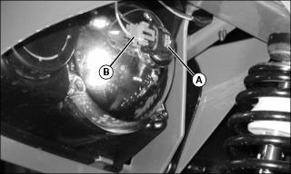
3. Rotate bulb socket (A) 1/8 of a turn counterclockwise and remove socket from housing.
4. Disconnect wire connector (B) from socket. Discard the bulb/socket assembly.
5. Connect wiring connector to new bulb/socket assembly. Install the assembly into housing and rotate 1/8 turn to lock in place.
Replacing Instrument Panel Bulbs
1. Park the vehicle safely. (See Parking Safely in the SAFETY section.)
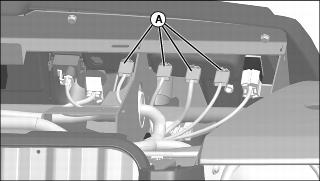
4. Reach under instrument panel and remove appropriate bulb socket (A) from plastic housing.
• Rotate bulb socket 1/3 turn.
• Pull socket straight outward.
5. Remove bulb from socket. Discard bulb.
6. Install new bulb in socket.
7. Align and insert bulb socket into plastic housing. Turn socket 1/3 turn to lock in place.
Checking and Replacing Fuses
IMPORTANT: Avoid damage! The electrical system may be damaged if incorrect replacement fuses are used. Replace the bad fuse with a fuse of the same amp rating. |
1. Park machine safely. (See Parking Safely in the SAFETY section.)
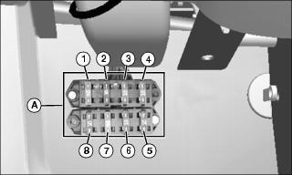
3. Pull fuse from fuse block (A).
4. Check visually for broken filament in fuse.
5. Push new fuse of correct amp rating into proper position in fuse block.