
Operating
Daily Operating Checklist
o Remove grass and debris from engine compartment, muffler area, and front grille, before and after operating machine.
o Check area below machine for leaks.
o Check brakes and park brake operation.
o Inspect driveline CV boots for tears or punctures.
o Check air restriction indicator.
Avoid Damage to Plastic and Painted Surfaces
• Do not wipe plastic parts unless rinsed first.
• Insect repellent spray may damage plastic and painted surfaces. Do not spray insect repellent near machine.
• Be careful not to spill brake fluid on machine components. Brake fluid may damage painted surfaces. Wipe up spilled brake fluid immediately.
• Be careful not to spill fuel on machine. Fuel may damage surface. Wipe up spilled fuel immediately.
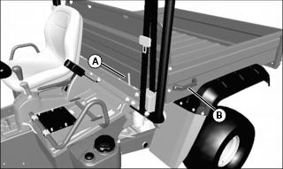
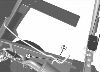
Using Hand Holds
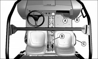
Hand holds are provided for passenger balance. When a passenger is present, they shall use two of the four hand holds at all times while the machine is moving. The dash bar (A), OPS handle (B), side rail (C) and grab handle (D).
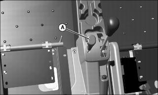
Adjusting Operator’s Seat
1. Stop machine and move transaxle shift lever to N (neutral) position.
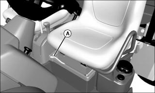
Picture Note: Seats removed for clarity.
3. Push lever (A) to the left.
4. Slide seat forward or rearward to desired position.
Adjusting Passenger Seat
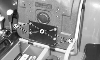
Picture Note: Rear position shown.
2. Hold onto seat and remove cap screws (A).
3. Slide seat to the forward (B) or rearward (C) position.
4. Position bottom of seat against bracket and align correct holes with holes in seat.
5. Install original hardware to secure seat.
6. Tighten seat bracket hardware to 10 N•m (7 lb-ft).
Using Seat Belt
NOTE: Shoulder harness is sensitive. An emergency lock device is built into the belt for your protection. To engage harness, pull harness slowly. Attempting to pull too fast or in a jerking motion will engage the locking mechanism and the harness will not release.
Periodically inspect seat belts for wear or damage. See Inspecting Seat Belt in the SERVICE MISCELLANEOUS section.
Fasten Belt
1. Grasp outer seat belt connector (A) from behind seat, pull out and across body to inner connector (B), at inside of seat.
2. To adjust outer connector for best fit, squeeze the upper (C) and lower (D) halves of outer connector together and adjust connector up or down along belt.
3. Push outer connector firmly into inner connector until it locks.
Release Belt
1. Press red button on inner connector to release seat belt.
Testing Safety Systems

The safety systems installed on your machine should be checked before each machine use. Be sure you have read the machine operator manual and are completely familiar with the operation of the machine before performing these safety system checks.
Use the following checkout procedures to check for normal operation of machine.
If there is a malfunction during one of these procedures, do not operate machine. See your authorized dealer for service.
Perform these tests in a clear open area. Keep bystanders away.
Testing the Safety Start System
1. Sit on the operator’s seat.
2. Put key switch in OFF position.
4. Move transaxle shift lever forward to the high range position.
5. Turn key switch to start position. Engine should not crank. Turn key switch off.
6. Move transaxle shift lever to reverse position.
7. Turn key switch to start position. Engine should not crank. Turn key switch off.
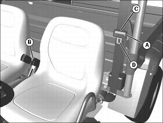
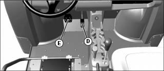
Using Park Brake
Always lock the park brake and remove the key before leaving the machine unattended. |
Locking the Park Brake:
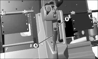
Picture Note: Seats removed for photo clarity.
1. Push down on brake pedal to hold machine in place.
2. Pull up on lever (A) and lock lever into position engaging park brake.
Unlocking the Park Brake:
1. Push down on brake pedal to hold machine in place.
4. Release lever down completely.
Using Key Switch
Picture Note: Key switch label.
A - STOP Position - With key in STOP position, all switched power is off, and engine should not run.
B - Run Position - Turn key from STOP to this position and all switched power circuits will be on.
C - Start Position - Turn key to start position to crank the engine. Release key after engine has started and it will automatically return to the run position. The engine will continue to run.
Using Headlights
Ignition switch/Key must be in the run position to operate the lights. If the Ignition switch/key is in the run position and the engine is not running, the battery will discharge if the lights are allowed to remain on for an extended period of time.
• Press top of light switch to turn headlights on.
NOTE: Be sure to turn lights off and turn the ignition switch/key to STOP position, or lights will discharge battery.
• Press bottom of light switch to turn headlights off.
Using and Checking Instrument Panel
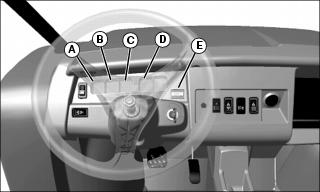
A - System Diagnostic Light - This light will come on for up to 4 seconds when key is turned ON. The light will flash when sensors malfunction. If light is active, stop machine and shut off engine. If light is active after restart, contact your John Deere dealer.
B - Engine Oil Pressure Light - This light will turn on when the ignition key is in the ON position and the engine is not running. If this light turns on while the engine is running, engine oil pressure is too low. Stop engine.
C - Engine Coolant Temperature Light - This light will turn on for several seconds after the ignition key is turned from the STOP position to run position. It will begin to flash when the coolant temperature reaches an overheat condition. If coolant temperature continues to rise, the engine will switch to a “power save” mode and the light will remain continuously on until the temperature decreases. If this light flashes or remains on during operation, remove load on machine immediately. Ensure fan is operating and that there is no blockage of the radiator. Check coolant level only when radiator is cool enough to touch with bare hands.
D - Park Brake Light - This light will turn on when the key switch is in the ON position and the park brake is partially or fully engaged into the locked position.
E - Hour Meter - The hour meter shows the accumulated number of hours the engine has run. The hour meter displays hours with the key in the ON position, and accumulates and displays hours when the engine is running. The hour meter is intended to provide a means of monitoring machine usage for maintenance purposes. Use the hour meter to determine when your machine has reached the recommended service intervals.
Using Accessory Outlet
NOTE: Accessory must be rated at 10 amps or less.
The accessory plug does not turn off with the key switch. Items connected to the accessory plug will continue to draw power, discharging the battery.
• Remove 12-volt outlet cover and install accessory cord in outlet.
• Install cover in outlet after use.
Using Turn Signal Switch (If Equipped)
NOTE: Turn signals will continue to flash when the ignition switch/key is in the STOP position, discharging the battery.
• Press at left end of turn signal switch to signal a left turn.
• Press at right end of turn signal switch to signal a right turn.
• Press at opposite end of turn signal switch until switch is centered to turn signal light off.
Using Hazard Lights (If Equipped)
NOTE: Hazard lights will continue to flash when the ignition switch/key is in the STOP position, discharging the battery.
• Press at top of hazard light switch to turn hazard lights on.
• Press at bottom of hazard light switch to turn hazard lights off.
Using Front Blade Switch (If Equipped)
• Press at top of front blade switch to raise blade.
• Press at bottom of front blade switch to lower blade.
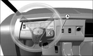
Using Speed Limiter Key Switch (If Equipped)
Speed limiter key switch is a 2-position switch used to limit maximum vehicle speed.

• Insert key to turn switch (A) to either position.
• Key can be left in or removed during operation.
• Maximum vehicle speed with switch turned clockwise to OFF position is 30 mph. Maximum vehicle speed with switch turned counterclockwise to ON position is 20 mph.
Using Storage Tray
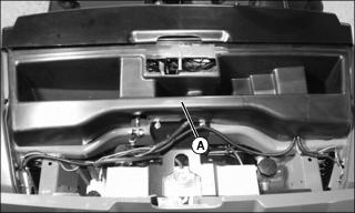
Storage tray (A) is located in front of machine under the hood. This is a convenient location to carry personal articles such as an Operator’s Manual, spare parts, first aid kit, and/or tools. The storage tray has a total volume of 7210 cc (440 in.).
1. Open hood to access the storage tray.
2. Secure all items to prevent damage from movement while operating the machine.
Starting the Engine
1. Sit on operator seat. Do not start engine at this time.
2. Push down on accelerator pedal to check free movement of pedal assembly. Release pedal.
NOTE: The machine has a neutral start safety switch. The engine will not start unless the transaxle shift lever is in N (Neutral) position.
3. Verify that transaxle shift lever is in N (Neutral) position.
4. Verify that park brake is locked.
5. Turn key switch to the ON position.
6. Check that the oil pressure indicator light is on.
7. Turn key to START position.
IMPORTANT: Avoid damage! Starter may be damaged if operated continuously for extended periods of time. Allow starter to cool down after several starting attempts. |
8. Release key to the ON position when engine starts.
• If engine does not start within five seconds, turn key to OFF position and wait ten seconds before trying to start again.
• In very cold conditions, attempt starting engine three times only, then wait 5 minutes before trying again. This will allow time for starter to cool and prevent damage to starter.
IMPORTANT: Avoid damage! Do not operate the engine at full throttle or under load until engine has warmed up, or engine damage could occur. |
9. Run engine at half speed for 2 or 3 minutes to warm the engine.
Stopping Engine
Always lock the park brake and remove the key before leaving the machine unattended. |
IMPORTANT: Avoid damage! Do not stop engine immediately after hard or extended operation. Keep engine running at low idle for about 2 minutes to prevent heat build-up. |
2. Move transaxle shift lever to N (Neutral) position.
4. Turn key switch to OFF position.
Using Travel Controls
2. Allow engine to come to a low idle speed.
NOTE: Always shift into low range when operating on wet or uneven terrain, or when towing or pushing heavy loads.

• Forward - Push shift lever forward to either high (A) or low (B) range.
• Reverse - Push shift lever to left, then pull rearward to reverse (C) gear.
4. Use the traction assist and/or 4WD-On-Demand as needed.
5. Look in the direction the vehicle will travel.
6. Push down accelerator pedal (D) slowly and smoothly to begin machine travel.
7. Release accelerator and apply brake pedal (E) evenly and firmly to slow down or stop.
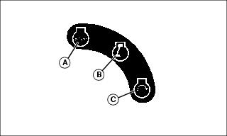
Using Traction Assist
Traction Assist (A) provides better traction when rear wheels start to slip. Engaging the traction assist will cause both rear wheels to turn together at equal speed.
Engaging the Traction Assist:
IMPORTANT: Avoid damage! Incorrectly engaging traction assist may damage the transaxle. Reduce speed before engaging or disengaging traction assist. |
1. Stop or reduce engine speed to 1\3 throttle or less.
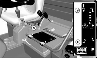
2. Push traction assist lever (A) forward to locked position (B):
• Traction assist will remain engaged as long as lever is forward.
Disengaging the Traction Assist
NOTE: To ensure true disengagement of traction assist, you must equalize torque on both axles.
1. Stop or reduce engine speed to 1/3 throttle or less.
2. Drive the vehicle straight ahead at a constant speed.
3. Pull lever rearward to unlocked position (C).
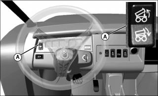
Using 4WD On-Demand
4WD On-Demand enables the front wheels to drive, but torque will not be applied until rear wheels begin to slip.
IMPORTANT: Avoid damage! Engaging 4WD On-Demand when the machine is stopped and the rear wheels are spinning will damage the gears. |
• Push in on top of 2WD/4WD switch (A) to enable the 4WD On-Demand system.
• Push in on bottom of switch to disable the system.
Tips for operating 4WD On-Demand:
NOTE: Occasionally the 4WD On-Demand system will not disengage after a change in vehicle travel direction. This is known as “wedging.” If this does occur, the vehicle will exhibit higher than usual steering efforts and driveline wind-up. To disengage (un-wedge) the system, reverse the direction of vehicle travel.
• Maintain recommended front and rear tire pressures to ensure optimum performance on all surface conditions.
• Disable 4WD On-Demand when driving machine on paved or hard packed surfaces to increase front tire life and reduce drive train wear.
Raising and Lowering Cargo Box
Manual Lift
1. Park the vehicle safely. (See Parking Safely in the SAFETY section.)
3. Release latch (A) by pushing inward toward center of machine. Raise cargo box manually with lift handle (B) on side of cargo box.
4. Push support rod (C) down to lock into slot (D) when cargo box is fully raised.
5. To lower cargo box, raise cargo box slightly using lift handle.
6. Release support rod from latch slot by pulling up on lower end of rod.
NOTE: Lowering the box completely will allow the support rod to latch at the front of cargo box.
7. Slowly lower cargo box. Support rod will slide along slotted channel.
8. Push down on cargo box handle until support rod latches into cargo box with an audible snap.
Power Lift (Optional)
1. Park the vehicle safely. (See Parking Safely in the SAFETY section.)
3. The cargo box switch (A) is located on the left side of the instrument panel.
4. Raise cargo box by pressing and holding top of switch (A). Release switch when box is at desired dump height or when reaching maximum height.
NOTE: Allowing the Power Lift hydraulics to operate at pressure relief briefly (less than one second) after cargo box is fully lowered will help keep cargo box secure and reduce rattling caused by travel vibrations.
5. Completely lower cargo box by pressing and holding bottom of switch (A).
Operating the Tailgate
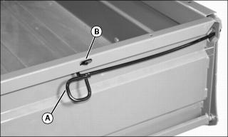
1. Push in and down on loop (A) of tailgate latch rods to unhook rods from slot (B) in tailgate.
2. Pull latch rods out and down.
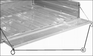
3. Lower tailgate until it rests on ends of latch rods (C).
IMPORTANT: Avoid damage! Lower tailgate completely to unload cargo box only. Never drive with the tailgate hanging down. Tailgate can contact tires and cause damage. |
4. To raise tailgate, slowly push tailgate upward. Push inward and upward on loop of latch rod to engage rod in slot in tailgate.
Removing Tailgate
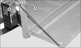
1. Remove and retain rubber hose sleeves from latch rod ends (A).
2. Raise tailgate slightly and rotate latch rods to disengage from slots (B) in cargo box sides.
3. Remove latch rods from sides of tailgate.
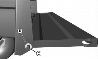
5. Remove retaining ring (C) and bushing (D) from each tailgate rod end.
6. Slide tailgate sideways so tailgate rod end is clear of the cargo box bracket.
7. Pull the detached end of tailgate away from the cargo box just enough to clear the cargo box bracket and allow the tailgate to slide in opposite direction to complete removal.
8. To install, reverse the steps.
Installing Tailgate Latch Rods
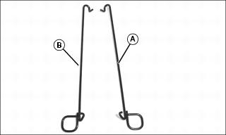
1. Identify right (A) and left (B) latch rods.
Picture Note: Left side shown.
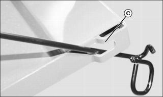
2. Route latch rod through tailgate opening (C) as shown.
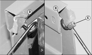
3. Raise tailgate slightly from horizontal position. Insert end of latch rod through slot (D) in cargo box bracket. Rotate rod around the bracket to secure.
4. Install rubber hose sleeve onto rod end (E).

5. Raise tailgate, push inward and upward on latch rod to engage rod in slot (F) in top rail.
Determining Vehicle Load Capacity
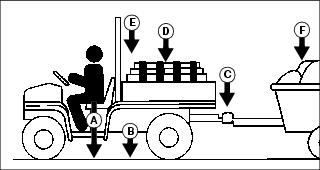
Factors in Determining Vehicle Load Capacity
NOTE: Optional equipment or attachments that are not standard equipment, must be included when determining gross vehicle weight, and may reduce cargo box capacity.
• 627 kg (1383 lb) - XUV Gas models
• 695 kg (1532 lb) - XUV Diesel models
b. Subtract the Gross Vehicle Weight (GVW) from the Gross Vehicle Weight Rating (GVWR).
c. The weight difference between the two numbers is the vehicle load capacity.
d. The Gross Vehicle Weight must be less than or equal to the Gross Vehicle Weight Rating. If GVW exceeds GVWR, remove excess weight from vehicle before operating.
Example:
The example below is for an XUV diesel vehicle with, a 350 lb cargo load, a 200 lb operator, 220 lb of attachments and options (such as a heavy duty brush guard, OPS poly roof, cargo box power lift kit, etc), towing a trailer with 50 lb of tongue weight.
GVW = 2352 lb (200 + 1532 + 50 + 350 + 220)
Vehicle Load Capacity = GVWR (3120) less GVW (2352)
Vehicle Load Capacity = 768 lb
The remaining vehicle load capacity of 768 lb can be used to haul additional operator, passenger, cargo, cart tongue and attachment weight.
Loading the Cargo Box
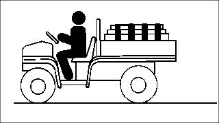
Maximum cargo box capacity on level terrain is 454 kg (1000 lb). Refer to Determining Vehicle Load Capacity in the Operating Section.
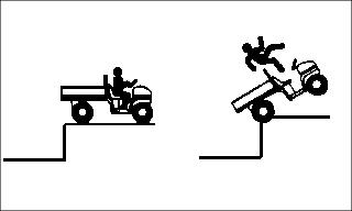
Reduce load by half when operating over rough, hilly, or steep terrain. Do not overload vehicle. Limit loads to those that can be safely controlled.
Reduce speed and exercise extreme caution when operating over rough, hilly, or steep terrain.
Securely anchor and evenly distribute loads in cargo box, when loading objects into vehicle. Shifting loads will affect stability.
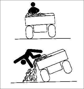
Avoid concentrated loads at rear or side of cargo box to prevent vehicle from tipping over. Be sure load is evenly distributed.
Because there is a big difference in weight between dry and wet sand, the only way of getting true weight of the load you are carrying is by using a scale.
For example, dry sand weighing 250 kg (550 lb) would be approximately 1/2 of cargo box volume.
Printed weight is normally on bagged and other material.
Emptying Cargo Box
1. Back up vehicle to dump site.
2. Park the vehicle safely. (See Parking Safely in the SAFETY section.)
IMPORTANT: Avoid damage! Stop emptying immediately if actuator clutch slippage occurs. Lower cargo box completely and remove excess load by hand before dumping. |
4. Raise cargo box to dump load.
5. Lower cargo box when empty.
6. Close tailgate. Do not drive vehicle with cargo box in raised position.
Towing Loads
• To provide adequate braking ability and traction, weight of towed load (trailer plus cargo) must never exceed the vehicle payload (operator plus passenger plus cargo box load).
• When operating over rough, hilly, or steep terrain and reducing cargo load by half, any towed load should also be reduced accordingly.
• Do not tow a load that exceeds 590 kg (1300 lb).
• Do not exceed a tongue weight of 59 kg (130 lb). (The tongue load of a trailer should be approximately 10% of the total trailer weight.)
• Tow load at a speed slow enough to maintain control.
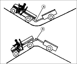
• Always use approved hitch and hitch point provided for the utility vehicle. Do NOT modify the hitch or hitch point in any way.
Using Correct Tires and Inflation
When replacing tires, always check the tire on the opposite side of the vehicle for excessive tread wear. Excessive variations in tread wear between opposite tires may cause the vehicle to pull to one side.
Tires
Use of John Deere approved original equipment or optional equipment is recommended. To ensure maximum machine performance and ride quality, do not mix size, type, or placement of tires. Failure to place tires per the guidelines could result in reduced machine performance, diminished traction and poor handling.
All Trail II tires
• 25 x 9.0-12 tires installed on front.
• 25 x 11.0-12 tires installed on rear.
AT489 tires
• 25 x 10.0-12 tires installed on front.
• 25 x 11.0-12 tires installed on rear.
These are directional tires. Directional type tires have directional arrows located on the tire sidewall. These tires should be installed with the directional arrow pointing in the forward direction of travel.
Inflation
IMPORTANT: Avoid damage! Over inflation may damage tires and diminish ride quality. Under inflation could cause wheel damage when riding over rough terrain. |
NOTE: Improper tire pressure can make it difficult to disengage 4WD On-Demand.
An accurate low pressure gauge is available at your John Deere dealer.
2. Check tire pressure with an accurate gauge.
3. Add or remove air, if necessary.
Tire Chains
Transporting Vehicle
NOTE: Space limitations may vary from one truck manufacturer to another. Short bed trucks do not have the necessary length requirement to accommodate the vehicle.
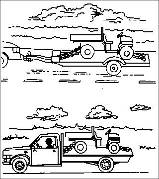
1. Back utility vehicle onto the trailer or truck.
2. Leave transaxle shift lever in forward or reverse gear.
3. Park vehicle safely (See Parking Safely in the SAFETY section.)
4. Fasten vehicle to trailer or truck with straps, chains, or cables.
5. Equip the trailer or truck with all the necessary lights and signs required by local, state, provincial, or federal laws.