Assembly
Identify Parts
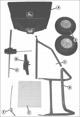
G - Axle and Gear Housing Assembly
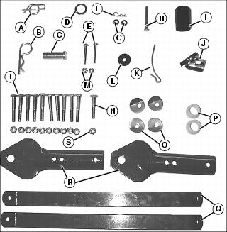
Bag of Parts
NOTE: *LP25010 contains 3 extra wheel washers.
Install Axle
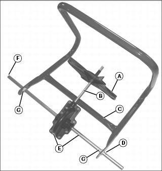
1. On 125 and 175 lb spreaders, install the disk (A) to the spinner shaft (B). (The 80 lb spreader already has the disk installed.)
2. Lay frame (C) down onto back side, as shown.
3. With the hole (D) in axle assembly (E) closest to the right side, and outer hole (F) on left side, install axle assembly (E) onto frame (C).
4. Install axle bushings (G) onto both ends of axle so collar of bushing is on the outside of the frame.
Install Wheels
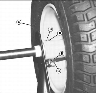
1. Install a wheel (A) on the drive side of the axle by inserting the clevis pin (B) through the holes in the wheel hub and axle. Secure using the drive wheel clevis pin (C).
• Drive wheel washers (D) should be placed on both sides of the wheel hub, as shown.
• Three extra wheel washers are provided with LP25010.
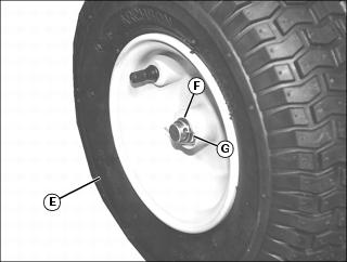
2. On the idle side of the axle, slide a second wheel (E) all the way onto the axle until the outer hole in axle shows. Install the wheel washer (F) to remove unwanted wheel movement. Secure wheel to axle using the locking clip (G).
Install Hopper

1. Position hopper (A) onto frame (B) with center hole in bottom of hopper through spinner shaft. Install so rate dial (C) (along with curved part of frame (D)) is facing towards front, as shown.
• 80 lb Spreader: Install four 1/4 x 1-1/2 in. bolts (E) with curved washers (F) from the inside of the hopper through the frame.
• 125 and 175 lb Spreaders: Install four 1/4 x 1-3/4 in. bolts (E) with curved washers (F) from the inside of the hopper through the frame.
2. Install four 1/4 in. locknuts from bottom. Tighten all hardware.

3. Slide felt washer (G) onto spinner shaft (H).
4. Install agitator (I) by sliding through hole in top of spinner shaft as shown.
Install Tow Bar
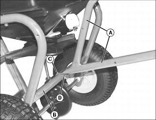
1. Position tow bar (A) over frame (B).
• 80 lb Spreader: Install 1/4 x 1-1/2 in. bolt (C) through tow bar and frame support and install locknut (D).
• 125 and 175 lb Spreaders: Install 1/4 x 1-3/4 in. bolt (C) through tow bar and frame support and install locknut (D).
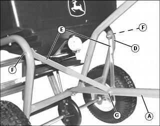
2. Fasten both braces (E) to the frame (D):
• 80 lb Spreader: Secure with 1/4 x 1-1/2 in. screws (F) with 1/4 in. locknuts.
• 125 and 175 lb Spreaders: Secure with 1/4 x 1-3/4 in. screws (F) with 1/4 in. locknuts.
3. Attach both braces (E) to tow bar (A):
• 80 lb Spreader: Secure with 1/4 x 1-1/2 in. screws (G) with 1/4 in. locknuts.
• 125 and 175 lb Spreaders: Secure with 1/4 x 1-3/4 in. screws (G) with 1/4 in. locknuts.
Install Hitch Plates

1. Fasten both sides of hitch plate (A) to tow bar (B):
• 80 lb Spreader: Secure with 1/4 x 1-1/2 in. screws (C) with 1/4 in. locknuts (D).
• 125 and 175 lb Spreaders: Secure with 1/4 x 1-3/4 in. screws (C) with 1/4 in. locknuts (D).
2. Install hitch pin (E) with spring locking pin (F).
Install On / Off Control Lever
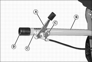
1. Fasten control lever (A) to tow bar (B) using two #10 x 1-1/2 in. screws (C) with #10 locknuts.
2. Push control lever (A) handle toward hopper.
3. Install handle cap (D) on the tow bar (B).
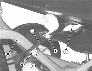
4. Slide control cable (E) wire into swivel connector (F) and secure with screw.
5. Route control cable (E) through cable clamp (G), and secure cable clamp to tow bar (B):
• 80 lb Spreader: Using one 1/4 x 1-1/4 in. screw (H) with 1/4 in. locknut.
• 125 and 175 lb Spreaders: Using one 1/4 x 1-1/2 in. screw (H) with 1/4 in. locknut.
6. Check to make sure control lever fully closes and opens the rate gate (I). If it does not, loosen screw (F) and adjust cable as necessary.