
Preparing Vehicle
Install Lift Assist Spring (Models with 38 Inch or 42 Inch Mowers)
NOTE: The X300R includes a lift assist spring as standard equipment. It is not necessary to order a Lift Assist Spring Kit for snowblower use on the X300R.
A lift assist spring is required to lift the snowblower; machines with 38 inch or 42 inch mowers, except the X300R, do not come equipped with this spring.
Order Lift Assist Spring Kit (AM136646) for models with 38 or 42 inch mowers, except the X300R.
Install Rockshaft Assembly
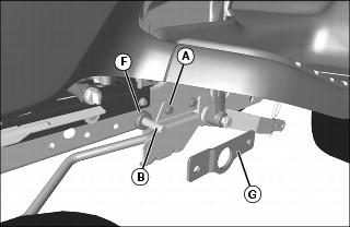
1. Remove bolt (A) and nut under left side of fenderdeck.
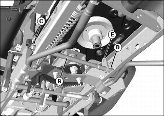
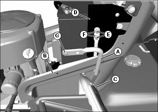
2. Install small end of rockshaft (B) through hole (C) on right side of machine frame, then pull large splined end through hole (D) on left side of machine frame. Make sure bracket (E) on rockshaft is pointing up.
3. Install one bearing (F) on end of shaft, with flange end of bearing against machine frame.
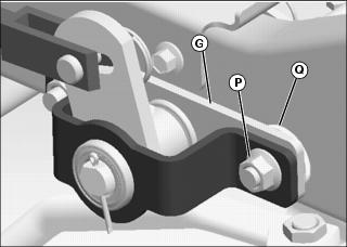
4. Install support bracket (G) on end of shaft.
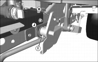
5. Install rockshaft bracket (H) facing upward, as shown. Secure with M6x40 clevis pin (I) and M2.5x16 cotter pin (J).
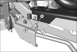
6. Secure right side of rockshaft (B) with bushing (K) and M2.5x20 cotter pin (L).
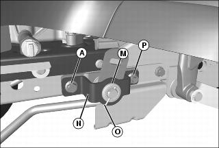
7. Install second bearing (M) onto mounting plate (N), and install assembly onto shaft. Secure with M3.2x32 cotter pin (O).
8. Secure front side of assembly with bolt (A) and nut, removed earlier.
Picture Note: X300R model shown.
• X300R only: Secure front side of assembly with M10x30 flange bolt and M10 flange nut provided.
9. Secure rear side of assembly with M10x30 flange bolt and M10 flange nut (P).
• X300R only: Secure rear side of assembly with M10x30 flange bolt and M10 flange nut (P), with M10x34ODx3W washer (Q) under bracket (G).
Install Rotation Handle Bracket
Picture Note: Model with mechanical lift shown.
2. Insert straight end of rotation handle bracket (A) through an existing access hole in the removable console panel (B), at the left side of the machine.
3. Align the two mounting holes in the straight end of the bracket with two square mounting holes in the left side console support plate (D). Install bracket by inserting two M8x20 carriage bolts (E) through the console support plate and the bracket, and securing with two M8 nuts (F). Tighten hardware.
4. Install M5 pan head screw (G), from the outside, into the round hole at the end of the bracket, and secure at the inside with an M5 nut. Tighten hardware. The screw head will serve as a locating pin for the chute and spout bracket.
Install Reflective Tape
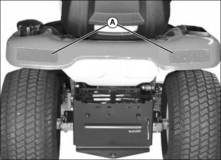
Apply reflective tape (A) to rear bumper of machines without reflectors.