
Installing
Preparing the Machine
NOTE: Read and complete the assembly procedures if installing the attachment for the first time.
Before installing attachment, remove mower from machine. (See Removing and Storing Mower section in machine operator’s manual.)
Machine Setup
• Check tire pressure of machine before operating machine.
X300R Model Only
• Both the mower deck and the discharge chute must be removed to use the snowblower.
• Either the collection hopper or the BM22916 Rear Deflector Kit must be installed to shield the transmission fan. The Rear Deflector Kit is recommended for maximum vehicle maneuverability.
Installing Ballast
Installing the recommended rear ballast will help counter-balance the weight of the snowblower. Remove ballast when the snowblower is removed. This will ensure proper operation of the machine when not removing snow.
Recommended Ballast (Except X300R)
NOTE: Rear Weight Bracket Kit, 4-Wheel Steer (BM24011) is required for rear weight use on 4-Wheel Steer models.
• Two 19 kg (42 lb) Rear Suitcase Weights (R66949).
Recommended Ballast (X300R)
NOTE: Tire chains are also recommended for use on the X300R.
• BM19123 Rear Wheel Weight Kit, includes two 14 kg (31 lb) plastic coated weights.
Remove Mower
1. Remove mower deck. (See Removing and Storing Mower section in machine operator’s manual.)
2. Remove mower deck drive belt and store with mower deck.
Installing Front Lift Assembly
Models with Mechanical Lift System
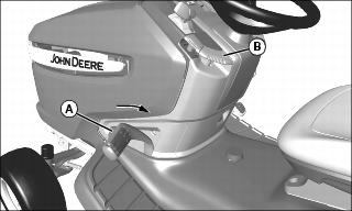
a. Pull lift pedal (A) back by hand to lower linkage to the lower/down position.
b. Pull lock lever (B) up to lock linkage in the lowered position.
X360 with Hydraulic LIft System
NOTE: On the X360, lift lever (B) raises and lowers the attachment linkage.
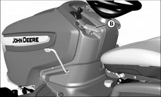
a. Push down on lift lever (B).
2. Park machine safely. (See Parking Safely in the SAFETY section.)
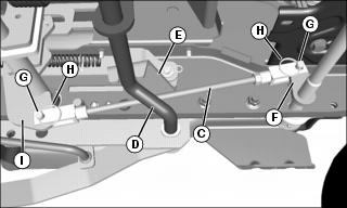
Picture Note: View from under right side of machine.
3. Raise shorter inner lift rod (C) into position between brake rod (D) and bracket (E), and install front yoke of lift rod to ear (F) of rockshaft. Secure with M10x28 drilled pin (G), installed from outside in, and locking ring (H).
4. Install rear yoke of shorter inner lift rod to ear (I) of shaft. Secure with M10x28 drilled pin (G) and locking ring (H).
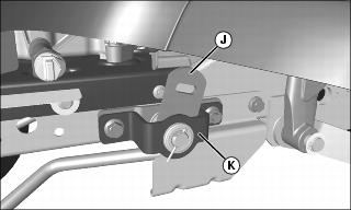
5. Verify that outside rockshaft bracket (J) does not interfere with the mounting plate (K):
• Check for interference, with attachment linkage in lower/down position.
NOTE: For X360 (hydraulic lift), engine will have to be started to raise attachment linkage. Raise slowly and check for interference carefully.
• Pull up on pedal (A), for mechanical lift models, or lift lever (B), X360 with hydraulic lift, and check for interference with attachment in raised/up position.
• If there is interference, disconnect rear end of inner rod, and rotate yoke to shorten or lengthen rod for proper fit. Install inner lift rod and repeat as necessary.
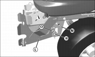
6. Align hole in front attachment hitch (L) with hole in front draft assembly (M) and install front draft pin (N). Secure with large M4.5 spring locking pin (O).
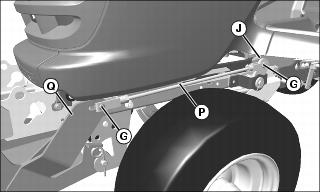
7. Install rear yoke of longer outer lift rod (P) onto rockshaft bracket (J) with M10x28 drilled pin (G) and locking ring.
8. Install front yoke of longer outer lift rod onto lift lever bracket (Q) with M10x28 drilled pin (G) and locking ring.
Installing Snowblower
Models with Mechanical Lift System

a. Pull lift pedal (A) back by hand to lower linkage to the lower/down position.
b. Pull lock lever (B) up to lock linkage in the lowered position.
X360 with Hydraulic LIft System
NOTE: On the X360, lever (B) controls the hydraulic lift system to raise and lower the attachment linkage. On models with mechanical lift system, the same lever only functions as a lock lever.

a. Push down on lift lever (B).
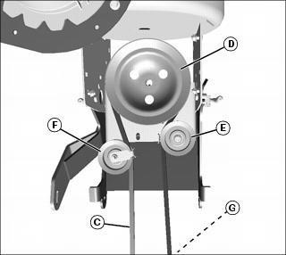
Picture Note: Top view with gearbox not shown for clarity.
2. Check snow blower drive belt (C) for wear and proper routing:
• Belt is routed around gearbox drive sheave (D), and inside of belt guards on idler sheave (E) and tensioning sheave (F), then to machine drive sheave (G).
• The tensioning spring connects to the tensioning sheave pivot arm, under the sheave.
• Belt must be installed on gearbox drive sheave from below, if it requires replacement.
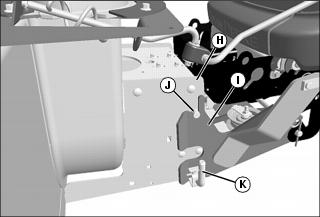
3. Align blower support (H) with front attachment hitch (I).
4. Secure blower support pins (J) onto top slots in front attachment hitch.
5. Pull L-pins (K), on each side, outward and lower blower support bracket. Release L-pins and lock blower support in place.
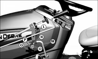
6. Align the slot at the bottom of the chute and spout bracket (L) over the locating screw at the outside of the rotation handle bracket (M).
7. Insert an M8x20 carriage bolt (N), from the inside, through the square mounting hole in bracket (M), and the mounting hole at the bottom of bracket (L). Secure with an M8.4 washer (O), 3/8 in. lock washer (P), and knob (Q).
8. Install drive belt on machine drive sheave:
a. Raise and block-up snowblower.
b. Pull on spring-loaded tensioning sheave arm to remove tension on belt.
c. Install belt on machine drive sheave (PTO clutch).
d. Release tensioning sheave arm.
e. Raise snowblower, remove support, and lower snowblower to ground.
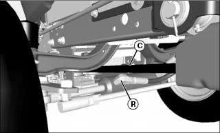
9. Check for interference between drive belt (C) and the left side fitting (R) on the machine steering cylinder. If necessary, rotate fitting down approximately ten degrees to eliminate interference and premature belt wear.
10. Raise snowblower fully to test lift adjustment:
Models with Mechanical Lift System
• Pull up slightly on foot pedal and push down on lock lever to unlock latch, then push foot pedal all the way down and lift lock lever to lock blower in raised position.The snowblower should be approximately 10.2 cm (4 in.) off the ground when in fully raised position.
• If blower will not lock in raised position, adjust lift height down and re-check.
X360 with Hydraulic Lift System
• Start engine and pull up on lift lever to fully raise blower. The snowblower should be approximately 10.2 cm (4 in.) off the ground when in fully raised position.
Check Tire Pressure
IMPORTANT: Avoid damage! To prevent tire damage, do not use more than maximum tire pressure shown on sidewall of tire. |
NOTE: See your Machine Operator’s Manual for correct tire pressure.