
Assembly
Identify Parts (25 Gallon Portable Sprayer)
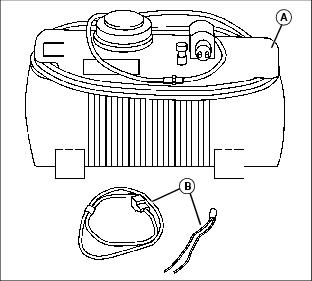
A - 25 Gallon Sprayer Base Unit (Tank with pump and hoses attached)
NOTE: No assembly is required for the 25 Gallon Portable Sprayer.
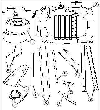
Identify Parts and Assemble (15 and 25 Gallon - Wheeled Sprayers)
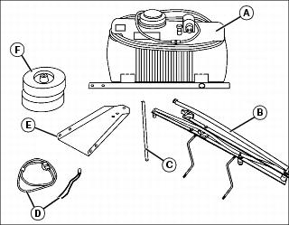
A - Sprayer Base Unit (Tank with pump and hoses attached)
B - Boom Assembly (25 gallon assembly shown)
Bag of Parts
Attach Hitch Frame
1. Remove hardware bags and wiring harness from inside tank.
2. Place tank and frame assembly, with tank frame (A) on top, onto top of shipping box (B) for installing hitch frame.
NOTE: When installing hardware, always install with nuts to the inside.
3. With tank frame (A) mounted to the inside of the hitch frame (C), align mounting holes on tank frame to mounting holes in hitch frame.
4. Install and tighten hardware (D):
• (4) 5/16 x 5/8 in. Flange Bolts
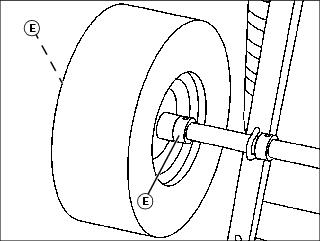
Install Wheels
NOTE: Install wheels so tire valve stems face to the outside of the sprayer frame.
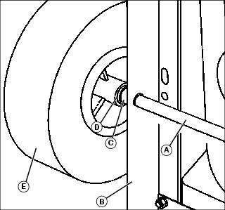
1. Install and center axle (A) into rear holes of tank frame (B).
2. Install axle spacer (C) and flat washer (D).
3. Install wheel (E), and then secure outside with locking collar.
4. Repeat for opposite wheel. Wheel hardware:
5. Tighten locking collars with a hex key wrench.
6. Lubricate wheel bearing grease fittings with recommended grease.
Install Hitch Assembly
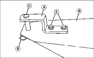
1. Install hitch clevis (A) on top of hitch frame (B) with hitch pin (C) and spring locking clip (D).
2. Install and tighten hardware (E):
• (2) 5/16 x 5/8 in. Flange Bolts
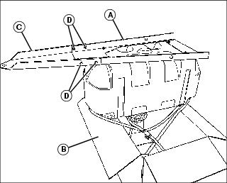
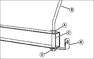
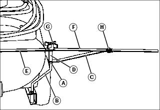
Install Boom Assembly
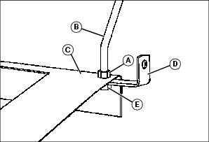
1. Install 3/8 in. nut (A) on boom support rod (B). Repeat for opposite side boom support rod.
NOTE: Install support, (D) facing toward rear of assembly and as far rearward as possible, as shown.
Boom assembly should be installed with hose connection tee facing forward.
2. Install entire spray boom and support rods through rear holes in tank frame (C).
3. Install support (D), 3/8 in. lockwasher, and a second 3/8 in. nut (E). Repeat for opposite side. Boom support hardware:
4. Do not tighten boom hardware until entire boom is in place.
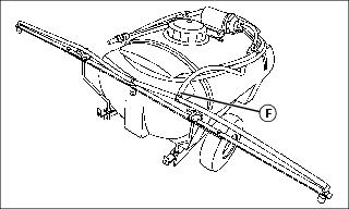
Picture Note: 25 gallon shown.
5. Connect tank hose (F) onto tee on boom hose.
Level Sprayer

Picture Note: 45 gallon shown.
1. Level, straighten and center boom with back of sprayer.
Install Wiring Harness to Battery
NOTE: Depending on the location of your battery, a wiring harness extension may be required. Part numbers are AM105666 (John Deere) or ST43485 (Superior Tech). See your John Deere dealer to order parts.
Tractors with a 12 volt receptacle requires a 12 volt plug adapter, part number ST43503 (Superior Tech). See your John Deere dealer to order parts.

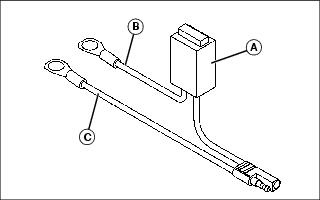
1. Fuse holder (A) should contain a 15 A / 32 V fuse. Make sure fuse filament is not broken.
2. Open hood. If battery is mounted low and behind the grille, carefully unsnap top of grille to provide access to battery terminals.
3. Remove nut from positive (+) battery cable clamp. Install red lead (B) onto clamp bolt. Install and tighten nut completely.
4. Remove nut from negative (-) battery cable clamp. Install black lead (C) onto clamp bolt. Install and tighten nut completely.
Install Wiring Harness Extension (For Machines With Upper Front-Mounted Battery)
NOTE: Wiring Harness Extension is required. See your John Deere dealer to order parts.
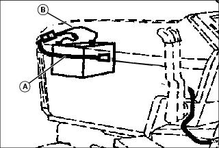
Connect wiring harness extension (A) to fused harness (B) at battery. Make sure the harness passes between the left side hood rods.
Install Wiring Harness Extension (For Machines With Lower Front-Mounted Battery)
NOTE: Wiring Harness Extension is required. See your John Deere dealer to order parts.
1. Route wiring harness extension through front frame hole.
2. Connect extension to battery lead plug. Then snap front grille in place.
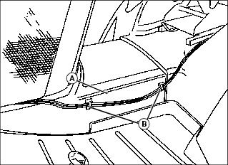
Install Wire Clips

1. Clean foot rest side panel (A) at left side of machine with mild detergent or isopropyl alcohol. Dry thoroughly.
2. Attach wire clips (B) to panel. Position the clips as shown so that sprayer main wiring harness will not interfere with deck height adjustment crank, if equipped.
Identify Parts and Assemble (45 Gallon - Wheeled Sprayer)
A - 45 Gallon Sprayer Base Unit (Tank with pump and hoses attached)
Bag of Parts
Clean Sprayer Tank
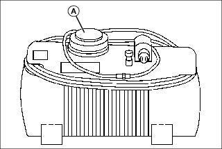
1. Remove tank filler cap (A).
2. Remove hardware bags and wiring harness from inside tank.
Attach Frame Rails and Hitch Frame
NOTE: When installing hardware, always install with nuts to the inside. Do not tighten any hardware until instructed.
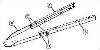
1. With frame rail (A) channels mounted to the inside of the hitch frame (B), align mounting holes in frame rails to mounting holes in hitch frame.
• (4) 5/16 x 5/8 in. Flange Bolts
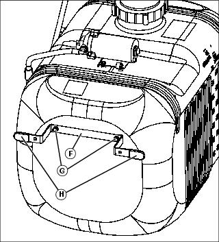
Install Hitch Assembly
NOTE: The 45 gallon sprayer hitch can be set up into four different positions. In order for the sprayer to completely empty the tank, the sprayer frame should be as level as possible. Adjust the sprayer drawbar to match the height of the machine hitch.
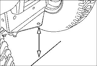
1. Measure distance from machine hitch to the ground.
NOTE: Assemble sprayer drawbar to match machine hitch height.
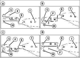
MX34794, MX34796, MX34779, MX34795
2. Install drawbar extension (E) (to bottom side of hitch frame), hitch clevis (F), hitch pin (G), and spring locking pin (H). Install and tighten hardware (I):
• (5) 5/16 x 1 in. Flange Bolts
Assemble Boom Support Rods
1. Install 3/8 in. nut (A) on boom support rod (B).
NOTE: Install support (D), facing toward rear of assembly, as shown.
2. Install boom support rod (B), boom spacer (C), support (D), and 3/8 in. nut (E). Boom support hardware:
3. Install boom support rods on both left and right frame rails. Do not tighten boom hardware until entire boom is assembled.
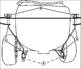
Install Sprayer Tank
IMPORTANT: Avoid damage! To prevent damage to sprayer after sprayer tank is installed, make sure all frame hardware is tightened. |
NOTE: When installing sprayer tank, position tank with pump towards the hitch end of frame.
1. Locate and install sprayer tank, with pump towards front of sprayer.
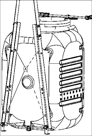
2. Install and tighten hardware (A):
• (4) 5/16 x 5/8 in. Flange Bolts
3. Tighten all frame hardware.
Install Axle
NOTE: Before tightening axle hardware, center axle with frame. When hardware is tight, axle should not move.
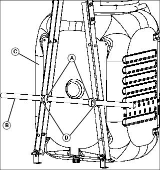
1. Install two locking collars (A) onto axle (B) and center axle with tank frame (C).
3. With axle centered in the tank frame, tighten locking collars with a hex key wrench.
4. Tighten 5/16 in. flange nuts included with hardware (D).
Install Wheels
NOTE: Install wheels so tire valve stems face to the outside of the sprayer frame.
1. Install locking collar (E) and wheel. Secure outside of wheel with second locking collar. Tighten locking collar with a hex key wrench.
2. Repeat for opposite wheel. Wheel hardware:
3. Lubricate wheel bearing grease fittings with recommended grease.
Install Boom
1. Install 3/8 in. nut (A) onto boom support rod (B).
2. Install boom support (C), spacer (D), center boom (E), boom extension (F), and locking knob (G).
3. Secure boom support and boom extension with 5/16 x 5/8 in. flange bolt and nut (H).
4. Repeat for opposite side. Retaining hardware:
• (2) Bolts, Flange, 5/16 x 5/8 in. (H)
• (2) Nuts, Flange, 5/16 in. (H)
Level Sprayer
Picture Note: 45 gallon shown.
1. Level, straighten and center boom with back of sprayer.
Install Hoses
NOTE: Prior to tightening the spray tip fitting cap nuts, make sure spray tips are parallel with boom.
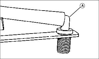
1. Install hose fitting (A) into all three boom holes.
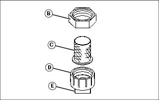
• Spray Tip Fitting Locknut (B)
• Spray Tip Fitting Cap Nut (D)
3. Install hose tender bracket (F) using two 5/16 x 5/8 in. flange bolts (G). Install plastic covers (H).
Install Wiring Harness to Battery
NOTE: Depending on the location of your battery, a wiring harness extension may be required. Part numbers are AM105666 (John Deere) or ST43485 (Superior Tech). See your John Deere dealer to order parts.
Tractors with a 12 volt receptacle requires a 12 volt plug adapter, part number ST43503 (Superior Tech). See your John Deere dealer to order parts.
1. Fuse holder (A) should contain a 15 A / 32 V fuse. Make sure fuse filament is not broken.
2. Open hood. If battery is mounted low and behind the grille, carefully unsnap top of grille to provide access to battery terminals.
3. Remove nut from positive (+) battery cable clamp. Install red lead (B) onto clamp bolt. Install and tighten nut completely.
4. Remove nut from negative (-) battery cable clamp. Install black lead (C) onto clamp bolt. Install and tighten nut completely.
Install Wiring Harness Extension (For Machines With Upper Front-Mounted Battery)
NOTE: Wiring Harness Extension is required. See your John Deere dealer to order parts.

Connect wiring harness extension (A) to fused harness (B) at battery. Make sure the harness passes between the left side hood rods.
Install Wiring Harness Extension (For Machines With Lower Front-Mounted Battery)
NOTE: Wiring Harness Extension is required. See your John Deere dealer to order parts.
1. Route wiring harness extension through front frame hole.
2. Connect extension to battery lead plug. Then snap front grille in place.
Install Wire Clips
1. Clean foot rest side panel (A) at left side of machine with mild detergent or isopropyl alcohol. Dry thoroughly.
2. Attach wire clips (B) to panel. Position the clips as shown so that sprayer main wiring harness will not interfere with deck height adjustment crank, if equipped.