
Service
Service Intervals
Beginning of Season
• Adjust and lubricate drive chain.
• Lubricate auger shaft, if equipped.
Every 25 Hours and End of Season
• Lubricate two grease points on driveshaft.
• Adjust and lubricate drive chain.
Grease
The following greases are preferred:
• John Deere Multi-Purpose SD Polyurea Grease
• John Deere Multi-Purpose HD Lithium Complex Grease
If not using any of the preferred greases, be sure to use a general all-purpose grease with an NLGI grade No.2 rating.
Wet or high speed conditions may require use of a special-use grease. Contact your Servicing dealer for information.
Gear Case Oil
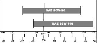
Use oil viscosity based on the expected air temperature range during the period between oil changes
The following John Deere gear case oil is preferred:
• GL-5 GEAR LUBRICANT® (SAE 80W-90)
The following John Deere gear case oil is also recommended if preferred oil is not available:
• GL-5 GEAR LUBRICANT® (SAE 85W-140)
Other gear case oils may be used if recommended John Deere gear case oils are not available, provided they meet the following specification:
• API Service Classification GL–5.
Adjusting and Lubricating Drive Chain
1. Park machine safely. (See Parking Safely in the SAFETY section.)
2. Disconnect driveshaft from machine.
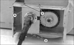
3. Move chain shield (A) left to provide tension on the chain. Deflection should be 4.7–10 mm (3/16–3/8 in.)
4. Adjust chain, if necessary:
• Loosen four lock nuts (B) on chain shield.
• Slide chain shield right or left until deflection measurement is right.
• Hold chain shield in place and tighten nut.
5. Rotate auger several turns and make sure chain has at least 4.7 mm (3/16 in.) deflection at all times.
6. Lubricate chain with John Deere TY6240 Chain Lube Spray or equivalent.
7. Start engine. Run snowblower briefly to distribute oil.
8. Stop engine. Wipe off excess oil.
9. Check condition of chain and sprockets. Replace if necessary.
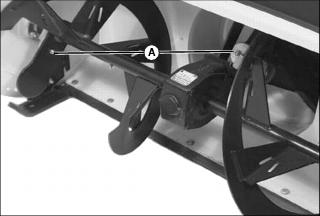
Checking Gear Box Oil
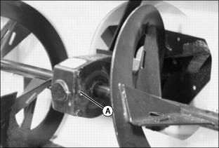
1. Remove filler plug (A). Oil should be even with bottom of hole.
2. If oil is low, add 80W-90 GL-5 Gear Oil.
Lubricating Auger Shaft
• Lubricate grease fittings (A) with John Deere Moly High Temperature EP Grease or an equivalent.
Lubricating Driveshaft
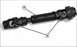
• Lubricate driveshaft grease fittings (A) with John Deere Moly High Temperature EP Grease or an equivalent.
Replacing Shear Bolt
IMPORTANT: Avoid damage! Replacement shear bolts must be same as original shear bolts on attachment: |
NOTE: When the auger hits an object, a shear bolt may break. This breakage helps prevent damage to rotor and snowblower. Replace broken shear bolts.
1. Park machine safely. (See Parking Safely in the SAFETY section.)
2. Remove broken shear bolt (A), one from each end, or one from impeller.

3. Turn auger or blower impeller to line up holes in shaft. Remove spare shear bolt (B) from snowblower.
4. Install bolt and nut. Tighten so that the two paddles that the shear bolts connect are touching. Do not overtighten nut.
5. Find and correct the cause for shearing.
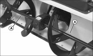
Servicing Scraper Blade
1. Check scraper blade for wear or damage.
3. Place wood blocks under collector assembly.
4. Lower attachment onto blocks.
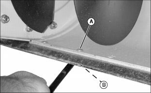
5. Remove nuts from bolts (A).
6. Turn scraper blade (B) end-for-end or replace blade if both sides are worn.
Removing Discharge Chute Cables
NOTE: When removing the black cable shield (A) an angle bracket will fall from underneath the attachment. This bracket needs to be installed again when the black cable shield is installed.
1. Park machine safely. (See Parking Safely in the SAFETY section.)
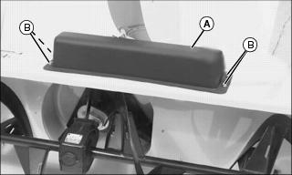
2. Remove black cable shield (A) and angle bracket by removing four lock nuts and hex head bolts (B).
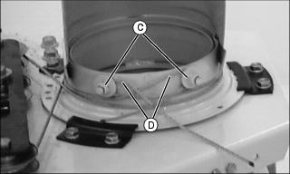
3. Loosen two lock nuts (C), from threaded studs on discharge chute.
NOTE: For ease of assembly and proper cable routing, remove one cable at a time.
4. Remove each cable (D) from attachment.
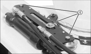
5. Remove cables from pulleys (E).
6. Install new cables on pulleys.
Replacing Discharge Chute Cables
Replacing Right Cable
IMPORTANT: Avoid damage! Hydraulic cylinder plunger must be in the retracted position (all the way in the cylinder) when beginning this procedure. |
NOTE: For ease of assembly and proper cable routing, replace one cable at a time. Route right cable around attachment first.
1. Rotate discharge chute to the right (as viewed from seat) to retract hydraulic cylinder plunger.

2. Standing at rear of attachment, put cable through hole (A).
3. Wrap cable around middle pulley (B), and around right pulley (C).
4. Wrap cable counterclockwise around discharge chute and put it around threaded stud and behind washer and lock nut (D).
Replacing Left Cable
IMPORTANT: Avoid damage! Hydraulic cylinder plunger must be in the retracted position (all the way in the cylinder) when beginning this procedure. |
NOTE: For ease of assembly and proper cable routing, replace one cable at a time. Route right cable around snowblower first, then route left cable.
1. Rotate discharge chute to the right (as viewed from seat) to retract hydraulic cylinder plunger.
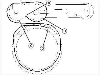
2. Standing at rear of attachment, put cable through hole (A).
3. Wrap cable around middle pulley (B), and around left pulley (C).
4. Wrap cable clockwise around discharge chute and put it around threaded stud and behind washer and lock nut (D).

Picture Note: Both cables installed.
IMPORTANT: Avoid damage! Make sure you install the long bolts through the black cable shield and bracket. |
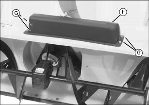
5. Install cable shield (F) and angle bracket and fasten with four hex head bolts (G) and lock nuts.