
Assembly
Charge and Connect Battery
1. Remove and discard the red positive (+) protective cap from the positive (+) battery terminal.
• Battery is fully charged at 12.6 volts.
3. Connect positive (+) battery cable to battery.
4. Connect negative (–) battery cable.
5. Apply general purpose grease or silicone spray to terminal to help prevent corrosion.
6. Slide red cover over positive battery cable.
Install Steering Wheel
1. Install steering wheel onto steering shaft. Turn steering wheel to position front wheels straight and facing forward.
3. Put John Deere Multi-Purpose lubricant or an equivalent on the steering shaft.
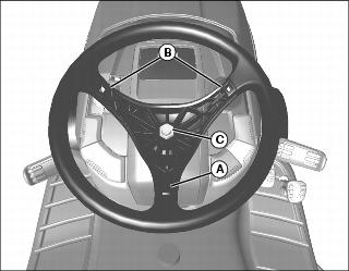
4. Install steering wheel onto steering shaft with one spindle (A) positioned at 180? at bottom of wheel and spindles (B) at approximately 45? at top of wheel.
5. Install nut (C) and tighten to 38 N•m (28 lb-ft).
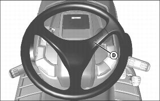
6. Install cover (D) so that the logo is on the right side facing up.
Install Seat Springs
IMPORTANT: Avoid damage! To prevent damage to seat switch and seat base, do not operate without suspension coils in place. |
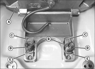
1. Raise seat (A) and install two springs (B) in one of three slotted areas in seat base.
• Move coils to front position (C) for softest ride.
• Move coils to middle position (D) for average ride.
• Move coils to rear position (E) for firm ride.
Install Anti-Scalp Wheels
NOTE: Anti-scapl wheels are not installed in correct hole position for operation.
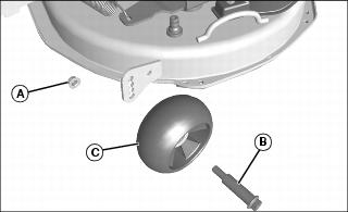
1. Remove nut (A) and shoulder bolt (B). Move wheel (C) to proper hole position. Secure with shoulder bolt and nut. Tighten nut to 34 N•m (25 lb-ft).
2. Adjust mower level before operation.
Install Grass Collector
Hopper Parts
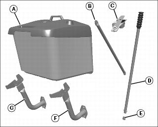
Assemble Hopper
1. Fold down hinged tube (A) as shown.
2. Install two support tubes (B) (one on each side), and secure bottom side (C) with two M6x30 headed pins (D), 6.5 mm washers (E), and cotter pins (F).
3. Secure support tubes on pins on upper side (G) with 6.5 mm washers (E) and cotter pins (F).
4. Rotate the hopper assembly so the bottom side is up, and unfold grass bag (H) into the open position. Snap clips (I) on grass bag to three sides of tube frame assembly.
5. Push grass bag end clips (J) onto front end of upper tube (K), and slide slightly rearward under hopper top (L).
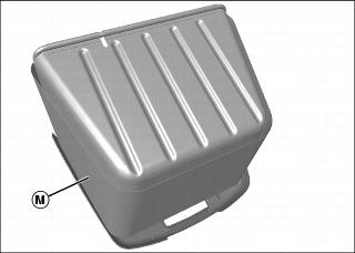
6. Open grass bag zipper to obtain open pocket area; zipper is found on the lower, inner side of grass bag curtain (M). Insert rubber sound mat into open pocket, so the letter “B” on sound mat will be visible on the inside bottom of the grass bag. Close zipper.
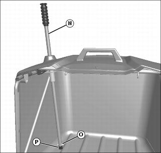
7. Rotate hopper assembly to the upright position, and install dump handle (N) into hopper assembly. Install a M6x35 bolt (O) and M6 locknut on end of dump handle. Install plastic cap (P) onto end of handle.
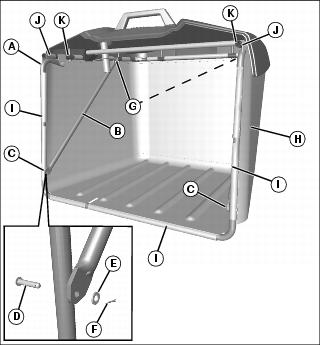
Install Hopper
NOTE: Left support arm is slightly different than right support arm. Install arms so top rear surfaces curve inward.
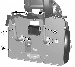
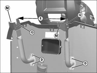
1. Install left (A) and right (B) hopper support arms onto back plate (C), using hardware (D) already on machine. Note differences in left and right arms. Snug hardware enough to allow later adjustments to the arms.
2. For initial adjustment, rotate the arms so the outer top surfaces are 395 mm (15-35/64 in.) (E) apart.
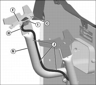
3. Install hopper presence switch assembly (F) to left hopper support arm (B), as shown, using one M6x20 carriage bolt and M6 locknut (G).
4. Route electrical harness (H) up the hopper support, as shown, and plug into switch (I). Secure the harness at three points (J) using three tie straps.
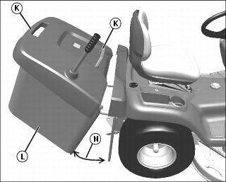
5. Use two handles (K) to raise hopper assembly (L) onto back portion (M) of support arms, and leave hopper assembly open at an approximate 20? angle (N).
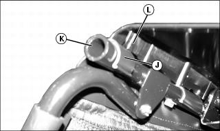
IMPORTANT: Avoid damage! Make sure arrows are aligned before closing hopper assembly. Damage could occur to machine and/or hopper if arrows are not aligned. |
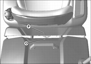
6. With hopper still at an approximate 20? angle, inspect that the center arrow (O) on the hopper aligns to the center arrow (P) on the machine. Move hopper, as necessary, to align the arrows.
7. Push the hopper forward, causing it to fall into the pivot (Q) on the support arms. Check again to be sure arrows align.
• If arrows do not align, remove the hopper and rotate the support arms, if necessary, to align the arrows and maintaining the 395 mm (15-35/64 in.) dimension (E). Tighten the support arm hardware (D) to 65 N•m (48 lb-ft). Install hopper back onto top of support arms at an approximate 20? angle, push hopper forward into the pivot on support arms, and make sure arrows align. Repeat adjustment procedure, if necessary.
9. Open and close hopper to check movement. Verify that hopper cannot be removed from machine when it is in the open position. Adjust as necessary.
10. Verify PTO operates with hopper installed and does not operate with the hopper off. With hopper off, hopper fill dash light should illuminate.
Check Engine Oil Level
Check engine oil level. (See Checking Engine Oil Level in the SERVICE ENGINE section.)
Check Tire Pressure
Check tire pressure. (See Checking Tire Pressure in the SERVICE MISCELLANEOUS section.)
Check Machine Safety System
Perform safety system check to make sure the electronic safety interlock circuit is functioning properly. Perform all tests. (See Testing Safety System in the OPERATING section.)