Assembly
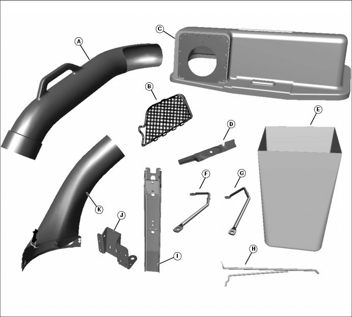
Identify Parts (42 and 48 in. Mower Deck)
Bagger and Hopper Parts
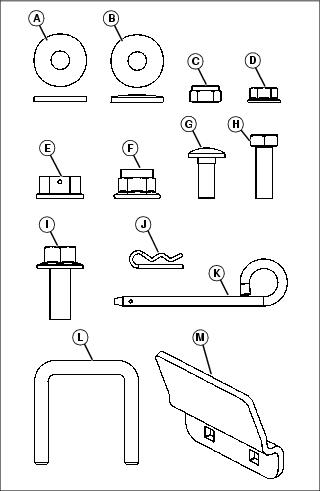
Bag of Parts
NOTE: Additional flat washer included for hopper top latch adjustment, if needed.
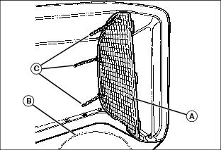
Assemble Hopper Screen to Hopper Top
1. Place hopper top upside down on a protective surface.
2. insert the hopper screen (A) inside the hopper top so it fits between tabs located between chute hole (B) and side of hopper top.
Fasten hopper screen to tabs with three tie straps (C). Put tie straps through holes in hopper top tabs and slots in screen.
3. Pull tie straps tight and cut off excess.
Assemble Support Rod to Mounting Post
Picture Note: 2008 and older version.
Picture Note: 2009 and newer version.
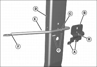
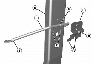
1. Fit tabs (A) on support rod bracket (B) into slots (C) on mounting post (D).
2. Insert support rod (E) between support rod bracket and mounting post:
• When viewed from rear, the longer end (F) of rod (E) should be faced toward the left.
• Flat side of drilled ends on support rod must be facing down.
• Tab (G) on support rod must fit into slot (H) on support rod bracket before tightening.
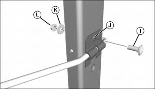
3. Insert M8x20 carriage bolt (I) through support rod bracket and hole (J) in mounting post.
4. Secure bolt with M8.4 flat washer (K) and M8 locknut (L).
Assemble Latch Rod to Mounting Post
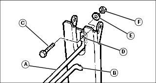
1. Insert lower part of latch rod (A) through hole (B) in mounting post.
2. Fasten upper part of latch rod with hex bolt (C) through latch rod end (D) and post hole, and secure with flat washer (E) and M8 lock nut (F).
Assemble Mounting Post to Hopper Top
NOTE: After hopper top is installed to the machine, raise and lower hopper top several times and adjust hardware if necessary for tightness.
1. Place hopper top upside down on a protective surface.
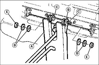
2. Install mounting post (A) to hopper top hinge (B).
3. Install M8x25 hex head bolts (C) from inside of hinge.
NOTE: Spring washers (D) must be installed with cup of washers facing each other. Do not over-tighten.
4. Install two spring washers (D) and M8 lock nut (E) on each hexhead bolt and tighten.
5. Fully raise and lower hopper top several times.
6. Tighten or loosen hardware to adjust hopper top hinge tightness.
Assemble Stop Bracket to Mounting Post Bracket
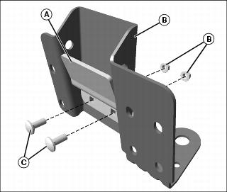
1. Position stop bracket (A) inside of mounting post bracket (B), aligning square mounting holes in stop bracket with the two slotted holes in the mounting post bracket. Secure with two M8x20 carriage bolts (C), installed from the inside out, and two M8 flange nuts (D). Do not fully tighten until mounting post is installed, to adjust properly for crosspin alignment.
Assemble Mounting Post Bracket to Machine
NOTE: Allow engine to cool before beginning kit installation. Some components are in proximity to muffler.
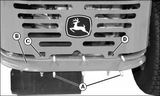
1. Install three U-bolts (A) around machine frame (B) from the front. Position left side U-bolt to the inside of engine shield mount (C) ,and the right side U-bolt to the outside of engine shield mount (D).
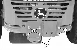
2. Assemble the rear hitch plate (E) onto the three U-bolts and secure with six 3/8 in. flange locknuts (F). Do not fully tighten hardware at this time.
Install Quick-Attach PIns
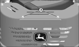
1. Remove and discard the two M8x20 flange head bolts (A) at the top rear of the engine cover, and replace with two M8 quick-attach pins from the bag of parts. Tighten hardware.
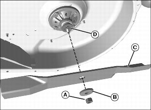
Install High Lift Blades (42 / 48 in. Cut and Throw)
1. Park machine safely. (See Parking Safely in the SAFETY section.)
2. Raise mower deck to gain access to mower blades. If necessary, remove mower deck.
3. Block mower blade being removed with a piece of wood to prevent it from spinning.
4. Remove standard mower blade:
• Loosen and remove nut (A), washer (B), and blade (C).
5. Install high-lift blade supplied with kit, making certain blade is properly seated against notched stud (D), and secure with original washer and nut.
