
Assembly
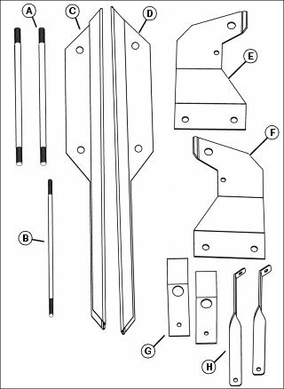
Parts List (X300, X500 Installation)
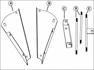
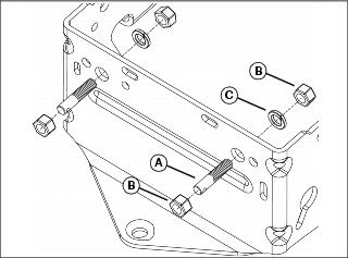
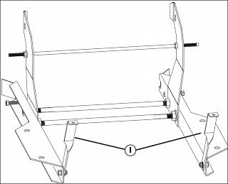
Assemble Tank (X300, X500)
NOTE: Distance from inside face to face of tank supports must be 13-1/2 inches (E), and can be adjusted with 1/2-in. nuts.

1. Position left and right tank supports (A and B) as shown.
2. Install one 1/2-in. rod (C) in rear position with four 1/2-in. hex nuts and two 1/2-in. lockwashers.
3. Install one 1/2-in. rod (D) in front slotted position with four 1/2-in. flange nuts.
4. Install 1/2-in. rod with drawbar (E) in front top with four 1/2-in. hex nuts and two 1/2-in. lockwashers.
5. Adjust 1/2-in. nuts to obtain distance of 13-1/2 inches (F) from inside face to face of tank supports.
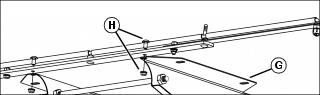
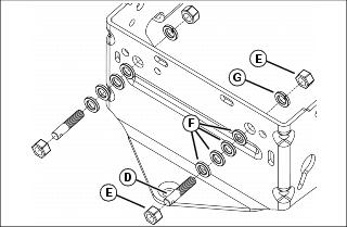
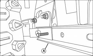
6. Install boom assembly (G) to frame with two 5/16 truss head bolts and 5/16 flange nuts (H).
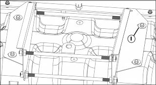
7. Secure tank assembly to left and right frames with four 3/8 flat washers and 5/16 x 5/8 flange bolts (I).
8. Position tank with spray wand to front. Tighten bolts to 14 N•m (10 lb-ft).
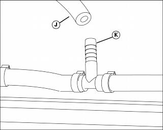
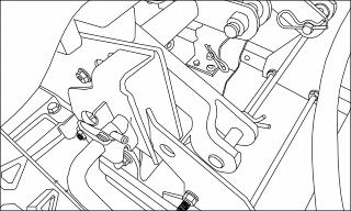
9. Connect boom hose (J) on tank assembly to tee fitting (K) on boom assembly (no clamp required).
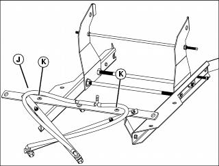
Install Anchor Mount and Sprayer (X300, X500)
Install Anchor Mount
1. 2-wheel steering tractor: Position threaded anchor pin (A) with hole to outside of frame and horizontal and loosely secure on rear frame of tractor with two 5/8 hex nuts (B) and one 5/8 lockwasher (C).
2. Install second threaded anchor pin.
3. 4-wheel steering tractor: Position threaded anchor pin (D) with hole to outside of frame and horizontal and loosely secure on rear frame of tractor with two 5/8 hex nuts (E), four 5/8 flat washers (F), and one 5/8 lockwasher (G).
4. Install second threaded anchor pin.
5. Install anchor bracket (H) to anchor pins and secure with spring clip pins (I). Adjust nuts on anchor pins to snug bracket and tighten hardware.
Spring clip pins should be loose enough to be removed for tractor anchor removal. Anchor pins can remain installed on tractor frame.
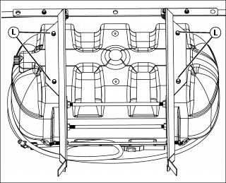
Install Sprayer
1. Angle sprayer and place top rod (A) into holding slots in anchor bracket.
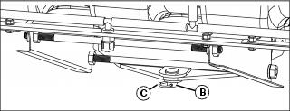
2. Place 3/4-in. drilled pin (B) through tractor hitch and slot of drawbar. Insert spring clip pin (C) to lock assembly in place.
3. Adjust rod positions in left and right frame slots to level sprayer.
Parts List (X700 Installation)
Assemble Tank (X700)
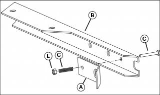
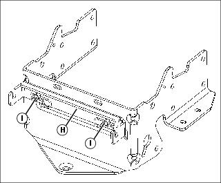
1. Secure latch levers (A) to left and right support channels (B) with 1/2 x 2 machine bolt (C), spring (D), and 1/4 Nylock nuts (E).
NOTE: Assemble support brackets as shown.
Lockwashers must be placed on inside of support channels.
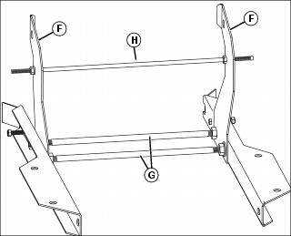
2. Install left and right support brackets (F) to left and right support channels with two 1/2-in. rods (G), four 1/2 lockwashers, and eight 1/2 hex nuts. Place lockwashers in inside of support channel.
3. Install 3/8-in. rod (H) to left and right support brackets with two 3/8 lockwashers, and four 3/8 flange nuts.
4. Install boom supports (I) to left and right support channels with two 5/16 x 5/8 flange bolts and 5/16 flange nuts.
5. Install boom assembly (J) to frame with two 5/16 truss head bolts (K) and two 5/16 flange nuts. Insert bolts down through boom with nuts on backside of boom supports.
6. Secure tank assembly to left and right support channels with four 5/16 x 5/8 bolts and four 3/8 flat washers (L). Position tank with spray wand to front.
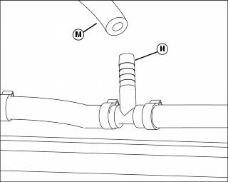
7. Connect boom hose (M) on tank assembly to tee fitting (N) on boom assembly (no clamp required).
Install Sprayer (X700)
NOTE: Ultimate series requires Click N Go brackets.
1. Slide support channels (A) over Click N Go, and lower pins until they click securely into place.
2. Lift back of sprayer until support bracket top holes line up with Click N Go bracket top pins. Use pins to secure sprayer in place.
Install Wiring Harness to Battery
NOTE: Depending on the location of your battery, a wiring harness extension may be required. See your John Deere dealer to order parts.
Tractor with a 12 volt receptacle requires a 12 volt plug adapter. See your John Deere dealer to order parts.

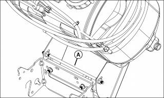
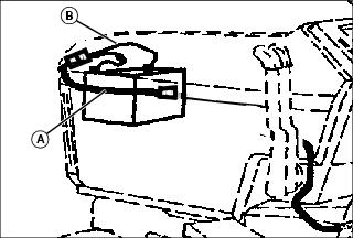
1. Fuse holder (A) should contain a 15 A / 32 V fuse. Make sure fuse filament is not broken.
2. Open hood. If battery is mounted low and behind the grille, carefully unsnap top of grille to provide access to battery terminals.
3. Remove nut from positive (+) battery cable clamp. Install red lead (B) onto clamp bolt. Install and tighten nut completely.
4. Remove nut from negative (-) battery cable clamp. Install black lead (C) onto clamp bolt. Install and tighten nut completely.
Install Wiring Harness Extension (For Machines With Upper Front-Mounted Battery)
NOTE: Wiring Harness Extension is required. See your John Deere dealer to order parts.
Connect wiring harness extension (A) to fused harness (B) at battery. Make sure the harness passes between the left side hood rods.
Install Wiring Harness Extension (For Machines With Lower Front-Mounted Battery)
NOTE: Wiring Harness Extension is required. See your John Deere dealer to order parts.
1. Route wiring harness extension through front frame hole.
2. Connect extension to battery lead plug. Then snap front grille in place.
Install Wire Clips
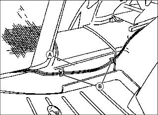
1. Clean foot rest side panel (A) at left side of machine with mild detergent or isopropyl alcohol. Dry thoroughly.
2. Attach wire clips (B) to panel. Position the clips as shown so that sprayer main wiring harness will not interfere with deck height adjustment crank, if equipped.