
Installing
Preparing the Machine
NOTE: Read and complete the assembly procedures if installing the attachment for the first time.
Before installing attachment, remove mower from machine. (See Removing and Storing Mower section in machine operator’s manual.)
Machine Setup
• Check tire pressure of machine before operating machine.
Installing Ballast
Installing the recommended rear ballast will help counter-balance the weight of the snowblower. Remove ballast when the snowblower is removed. This will ensure proper operation of the machine when not removing snow.
NOTE: Rear Weight Bracket Kit (BG20022) is required for rear weight use.
• Two 19 kg (42 lb) Rear Suitcase Weights (R66949).
Remove Mower
1. Remove mower deck. (See Removing and Storing Mower section in machine operator’s manual.)
2. Remove mower deck drive belt and store with mower deck.
Installing Snowblower
1. Slide frame under machine with rear hanger brackets on frame positioned under the rear mounting plates on the machine.
Picture Note: Upper drive components not shown.
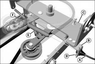
2. With frame on the ground, connect mower engagement cable (machines with manual mower engagement only).
a. Install mower engagement cable (A) in slot in cable bracket (B) at left side of drive system plate (C).
b. Secure cable in bracket with spring locking pin (D).
c. Hook end of cable spring (E) into slotted hole (F) in primary (upper) tensioning arm.
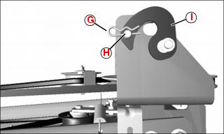
3. Remove spring locking pin (G) and drilled pin (H) that secures the latch (I) to the hanger bracket at both sides of the machine. Rotate the latch backwards to expose the slot in the hanger bracket.
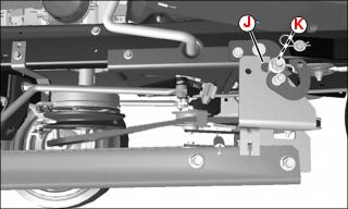
4. Lift the back of frame and align the slot (J) of the hanger bracket with the long bushing (K) at the rear mounting plate at each side of the machine.
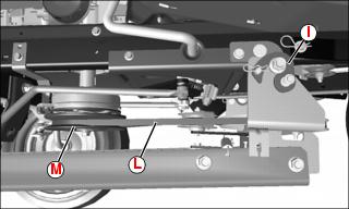
5. Slide the frame backwards to fully engage the hanger brackets, rotate the latch (I) to closed position on each side and secure with drilled pins and spring locking pins, removed earlier.
6. Install primary drive belt (L) on machine drive sheave (M).
NOTE: Adjustable lift link must be assembled with stud in low position (for maximum lift) for tractors with 15 in. front tires, or in high position (for minimum lift) for tractors with 16 in. front tires.
Picture Note: Lift link orientation for 15 in. front tires shown.
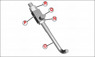
7. Assemble adjustable lift link to adjustable lift rod (one assembly per side):
• Thread M10 nut (N) onto adjustable lift rod (O).
• Slide adjustable lift link (P) onto lift rod with mounting leg (Q) toward the bottom (15 in. front tires) or the top (16 in. front tires), and secure with an M10 locknut (R).
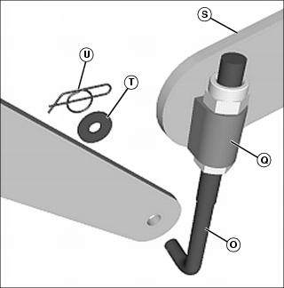
8. Install mounting leg of each adjustable lift link (Q) into front mounting plate (S), and pivot it downward.
9. Install lower end of each lift rod (O) into mounting hole in lift arm and secure with M10x30 OD washer (T) and locking cotter pin (U).
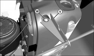
Picture Note: Spout control cable not shown. Additionally, machines up to SN -099999 shown. Chute control bracket for SN 100001- is similar.
11. Position chute control bracket (V) on console and install M6x45 carriage bolt (W). Install M6 serrated lockwasher, M6.4 washer and M6 wingnut on carriage bolt from underneath hood. Tighten securely.
13. Adjust lift height. See “Adjusting Lift Height” in Operating section.
Check Tire Pressure
IMPORTANT: Avoid damage! To prevent tire damage, do not use more than maximum tire pressure shown on sidewall of tire. |
NOTE: See your Machine Operator’s Manual for correct tire pressure.


