Troubleshooting
Using Troubleshooting Chart
If you are experiencing a problem that is not listed in this chart, see your authorized dealer for service.
When you have checked all the possible causes listed and you are still experiencing the problem, see your authorized dealer.
Blade Troubleshooting
If you are experiencing a problem that is not listed in this chart, see your authorized dealer for service.
When you have checked all the possible causes listed and you are still experiencing the problem, see your authorized dealer.
MX45936
MX45519
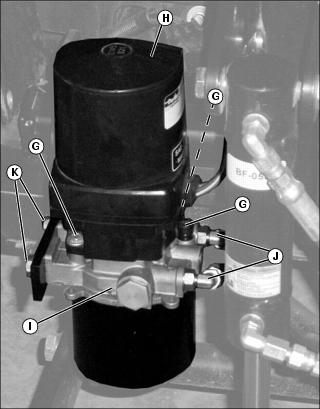
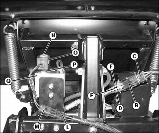
NOTE: Use two graphics above to follow steps within troubleshooting table.
IF
|
CHECK
|
PROCEDURE
|
1. Pump runs, but hitch does not move or is slow.
|
Check hydraulic fluid level, fill as necessary.
|
Remove fill cap (A). Fill pump with John Deere J20D hydraulic fluid and replace fill cap. Move blade left and right. Repeat this procedure 5 to 6 times to get the air out of the system. Refill with hydraulic fluid.
|
2. Pump runs, and is filled with hydraulic fluid, but still too slow.
|
Check hydraulic fluid level. If adequate, remove orifice.
|
Check the vehicle electrical system by jumping the battery with another vehicle and run the blade while the vehicle is being jumped. If this fixes the problem, then fix vehicle electrical system. Most common issue is an old battery not performing optimally. Replace old battery. On gas powered machines, you will need to have an alternator kit installed. On diesel powered machines, you will need to have a heavy duty alternator kit installed if you are using heater and/or lights.
|
3. Thermal breaker keeps kicking in.
|
Wait 2 minutes and it will reset.
|
Operating Blade with continued pressure on controller will cause the thermal breaker to kick in.
|
4. Hydraulic fluid leaking.
|
Check hoses and fittings for possible loose hydraulic fittings.
|
Tighten fittings to 20 N•m (180 in-lb). Refill with fluid and bleed system as directed in item #1.
|
5. Blade trips too easily.
|
A) Check spring tension.
B) Check to see if springs are bent or damaged.
|
A) The springs are attached to a bracket at the top of the blade. Tighten the nuts that hold this bracket on. Tighten 1/2 in. on each side. If blade still trips too easily, tighten additional 1/2 in. Repeat as necessary.
B) Replace springs.
|
6. Blade does not trip.
|
Springs.
|
The springs are attached to a bracket at the top of the blade. Loosen the nuts that hold this bracket on. Loosen 1/2 in. on each side. If blade still does not trip, loosen additional 1/2 in. Repeat as necessary.
|
7. Blade is not lifting either in the up direction and/or the down direction.
|
A) Check hydraulic fluid level.
B) Check to see if pump is bad.
C) Check electrical harness using this procedure.
|
A) See item #1 for filling and bleeding directions.
B) Tools/Material needed: Two 84 in. long 12 gauge jumper wires with alligator clips.
Procedure:
• Disconnect the blade from the hitch assembly by removing the two latch pins and the two hydraulic quick disconnects. Move the blade to the down position to relieve pressure when disconnecting hydraulics. Move the blade away from the hitch assembly.
• Disconnect pump electrical harness connector (B) from the harness electrical connector (C).
• Connect one of the jumper wires from the negative battery terminal to the black motor wire (D).
• Connect one of the jumper wires from the positive battery terminal to the green motor wire (E). Listen to the motor for operation - if the motor is not making a sound, the motor is bad and must be replaced.
• Alternate the location of the jumper wire from the blue wire (F) to the green wire (E) - back and forth. When the blue wire is connected the hydraulic cylinder on the hitch should contract and the hitch assembly move up. When the green wire is connected the hydraulic cylinder on the hitch should extend and the hitch assembly should move down. If the hitch still fails to move both in the upward and downward directions, recheck to make sure the pump is filled with hydraulic fluid. If the hitch still fails to move both in the upward and downward directions when alternating the connection of the jumper wire, the motor is bad and must be replaced. Disconnect pump electrical harness connector (B) from the harness electrical connector (C). Remove the two screws (G) and motor (H).
C) - If the hitch is working properly, the trouble is in the electrical harness or switch (see electrical harness and switch trouble shooting item #11 below).
|
8. Pump needs to be replaced if hydraulic fluid is leaking from the manifold.
|
Check if crack is in pump by seeing if fluid is coming out of manifold (I). Check to see if pump is working using procedure in "Blade is not lifting either in the up direction and/or the down direction" in item #5 above.
|
Tools Needed: Two 9/16 inch wrenches
Pump Replacement Procedure:
• Disconnect pump electrical harness connector (B) from the harness electrical connector (C).
• Disconnect the two hydraulic hoses from the two 90 degree flare fittings (J) that are attached to the pump and plug hoses to eliminate contamination and minimize fluid leakage. (Do not disconnect the two 90 degree flare fittings at this time.) Make sure to mark which hoses go to which fitting to verify they are on the same way when reinstalling. The dust covers are color coded blue and black for this.
• Disconnect the two mounting bolts (K) attaching the pump to the hitch assembly and remove the pump.
• On a table, place the new pump and old pump side by side. Notice the angles of the 90 degree flare fittings (J) with respect to the old pump. Remove one at a time, each 90 degree flare fitting from the old pump and attach it to the new pump at the same angle. Tighten both flare fittings to 20 N•m (180 in-lb).
• Attach the pump to the hitch assembly with the two mounting bolts.
• Connect the two hydraulic hoses to the two 90 degree flare fittings. Tighten to 1/3 turn past finger tight.
• Fill pump with John Deere J20D Hydraulic fluid and move blade up and down, waiting several seconds between each movement. Continue doing this for approximately 3 to 5 minutes. Refill with hydraulic fluid.
|
9. Blade is lifting in the up and down direction, but not left or right direction.
|
Check to see if Solenoid is functioning properly. If Solenoid is not functioning properly -- replace solenoid. If Solenoid is functioning properly, then trouble shoot electrical harness/switch using the electrical harness and trouble shooting procedure provided below in item #10.
|
Material needed: Two 84 in. long 12 gage jumper wires with alligator clips.
WE RECOMMEND TWO PEOPLE FOR THIS PROCEDURE
Procedure:
• Turn the vehicle key to the off position.
• Make sure the blade is connected to the hitch assembly by the two latch pins and the two hydraulic quick disconnects.
• Disconnect electrical harness connector (L) from the solenoid electrical connector (M). (The solenoid is located on top of the machined aluminum manifold located on top of the hitch assembly.)
• Connect a jumper wire from the negative battery terminal to one of the black solenoid wires.
• Connect a jumper wire from the positive battery terminal to the other black solenoid wire.
• Step away from the blade and into the vehicle. Turn the vehicle key to the on position. Utilizing your joystick, move the blade up and down. Then move blade left and right. If the blade fails to move left and right, the solenoid is bad and must be replaced. See item #8. If the blade is working to the left and right, the trouble is in the electrical harness or switch (see electrical harness and switch trouble shooting procedure - Item #11).
|
10. Solenoid needs to be replaced.
|
Check if solenoid is working by using procedure provided in Item #9 directly above.
|
Tools Needed: One 3/4 in. wrench and one 7/8 in. wrench.
Solenoid Replacement Procedure:
• Disconnect electrical harness connector (L) from the solenoid electrical connector (M).
• Remove nut (N) on top of solenoid and remove magnetic coil (O).
• Remove nut (P) on bottom of solenoid and remove solenoid from manifold (Q).
• Install new solenoid by tightening bottom nut of solenoid to 20 N•m (180 in-lb).
• Reconnect electrical connection between the solenoid and the electrical harness.
• Refill pump with John Deere J20D Hydraulic fluid as necessary.
|
11. Electrical harness or switch is not functioning properly.
|
Important! FIRST verify pump and solenoid are working correctly. This can be done using procedures in items #9 and #10 above. If the pump and solenoid are working, use the procedure to the right to test the harness.
|
Material Needed: Two 84 inch long 12 gage jumper wires with alligator clips.
Procedure:
• Important! Verify pump and solenoid are working correctly as described in above sections.
• Disconnect the joystick switch wire harness 6 pin connector to the main snow blade electrical wire harness.
• At the 6-pin main harness connector, jumper the pin with the Red wire to the pin with the blue (or black) wire. Verify the hitch moves UP.
• At the 6-pin main harness connector, jumper the pin with the Red wire to the pin with the Green wire. Verify the hitch moves DOWN.
• At the 6-pin main harness connector, jumper the pin with the Red wire to the pin with the Blue (or Black) wire and jumper the pin with the Red wire to the pin with the Orange wire. Verify the blade moves RIGHT
• At the 6-Pin connector, jumper the pin with the Red wire to the pin with the Green wire and jumper the pin with the Red wire to the pin with the White wire. Verify the blade move LEFT.
• If the movements are correct above, then replace the main snow blade harness. If any of the movements are incorrect above, replace the joystick switch harness.
• See Wiring Harness Troubleshooting story below for detailed description.
|
12 Cannot connect hydraulic hoses from blade assembly to hitch manifold.
|
Check to see if male or female disconnects are worn or damaged. If so replace them.
If fittings are not worn or damaged, use the procedure to the right to connect or disconnect fittings.
|
If you are in the vehicle, with the pump on, move the joystick to the left position for a second. Then the left hose (as viewed from the seat of the vehicle) can be disconnected or connected easily. Then move the joystick to the right position for a second. Now, the right hose (as viewed from the seat of the vehicle) can be disconnected or connected easily. If relieving pressure to both the male and female fittings does not work check for worn or damaged parts to the male or female fittings. Replace as necessary.
|
Wiring Harness Troubleshooting
If you are experiencing a problem that is not listed in the troubleshooting diagram, see your authorized dealer for service.
When you have checked all the possible causes listed and you are still experiencing the problem, see your authorized dealer.
Test Wiring Harness
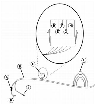
This diagram is intended to assist in troubleshooting the wiring harness if a problem exists with the blade control lever operating correctly. Use this diagram to determine whether the wiring harness is faulty or the blade control lever is faulty.

MX40150
Picture Note: Wire Harness Components
A - Breaker
B - Wiring Harness
C - 6-Pin Connector
D - Red Wire
E - Blue or Black Wire
F - Green Wire
G - White Wire
H - Orange Wire
I - Relays
J - Ground Wire
K - Positive Wire to Battery
Troubleshooting the wiring harness requires jumpering pins together from the 6-Pin connector (C) located on the wiring harness (B). To determine a problem with either the blade control lever or wiring harness, check proper hitch movement by doing the following:
• Disconnect the 6-Pin connector from the blade control lever.
• At the 6-Pin connector, jumper the pin with the Red wire (D) to the pin with the Blue (or Black) wire (E). Verify hitch moves DOWN.
At the 6-Pin connector, jumper the pin with the Red wire (D) to the pin with the pin with the Green wire (F). Verify hitch moves UP.
• At the 6-Pin connector, jumper the pin with the Red wire (D) to the pin with the Blue (or Black) wire (E), and jumper the pin with the Red wire (D) to the pin with the Orange wire (H). Verify blade moves LEFT.
• At the 6-Pin connector, jumper the pin with the Red wire (D) to the pin with the Green wire (F) and jumper the pin with the Red wire (D) to the pin with the White wire (G). Verify blade moves RIGHT.
NOTE: If hitch and blade movement is correct replace blade control lever. If hitch movement is incorrect refer to Blade Troubleshooting chart.
|


