
Service Transmission
Checking Transmission
The transmission is a sealed component. No maintenance is required on this transmission. If you suspect any transmission problems, please contact your authorized dealer.
Checking Transaxle Oil Level
The transmission is a sealed component. No maintenance is required on this transmission. If you suspect any transmission problems, please contact your authorized dealer.
Changing Transaxle Oil and Filter
The transaxles on these models require no maintenance. If you suspect transmission problems, contact your authorized dealer.
Checking and Adjusting Neutral Creep
Checking Neutral Creep
Check neutral creep with engine running, motion control levers in the start/shutdown position, park brake off, and machine on level ground.
If the machine creeps forward or reverse while motion control levers are in the start/shutdown position, adjust the motion control lever linkages.
Adjusting Neutral Creep
1. Park machine safely. (See Parking Safely in the SAFETY section.)
2. Remove style panel for better access to adjustment components (if desired):
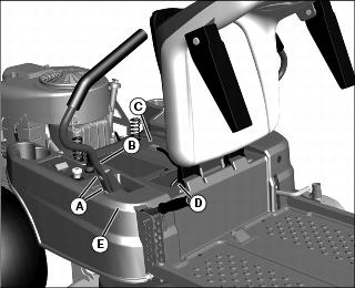
a. Remove two bolts (A) and steering arm (B).
b. Raise seat and disconnect wiring harness connector (C) from seat switch.
c. Remove two L-pins (D) to remove seat.
d. Remove seven push retainers from style panel (E) and remove style panel.
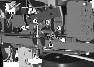
Picture Note: Right side of machine shown with machine parts removed for a more clear image.
3. On linkage side needing adjustment (right side shown), remove spring locking clip (F) and rod end (G) from pivot pin (H). Turn rod end (G) on rod (I) in (clockwise) to decrease forward creep and out (counterclockwise) to decrease reverse creep. Repeat procedure, as necessary, on opposite side. Install rod ends back onto arms and secure with spring locking clips.
4. Install style panel and push retainers, seat, seat switch and steering arm if previously removed.
Adjusting Tracking
If the machine does not track in a straight line while going in full forward position, the tracking requires adjustment.
1. Park machine safely. (See Parking Safely in the SAFETY section.)
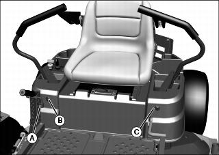
2. Adjust tracking with the 13 mm socket on the free end of the deck height adjustment lock pin (A) as follows:
NOTE: Tracking bolts limit top forward speed. If both levers hit against the tracking bolts, turn both bolts counterclockwise equal amounts until only one bolt contacts the lever. This will achieve maximum forward speed.
• If machine tracks to the left, turn tracking bolt (B) clockwise.
• If machine tracks to the right, turn tracking bolt (C) clockwise.
Cleaning Transaxle Cooling Fans
• Clear work area of bystanders. • Wear eye protection when using compressed air for cleaning purposes. |
1. Park machine safely. (See Parking Safely in the SAFETY section.)
Picture Note: View from front of machine.
2. Clean transaxle fan fins (A) and around exterior of each fan with a rag, brush or compressed air.
Checking and Replacing Transaxle/Transmission Drive Belt
NOTE: The transmission drive belts are self-adjusted using a spring tensioner and do not require a tension adjustment.
Checking Transaxle/Transmission Drive Belts
1. Park machine safely. (See Parking Safely in the SAFETY section.)
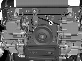
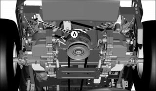
2. Inspect drive belt (A) for excessive wear, damage or stretching while in position on all machine sheaves.
Replacing Transaxle/Transmission Drive Belts
1. Park machine safely. (See Parking Safely in the SAFETY section.)
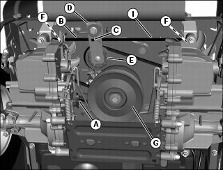
Picture Note: Components viewed from bottom.
3. Disconnect electric clutch wiring connector (A) from main wiring harness connector.
4. Insert a 3/8 in. ratchet or breaker bar into the square hole (C) on the idler arm (D), rotate the spring-loaded idler arm to relieve belt tension on the idler sheave (E) and remove the drive belt (B) from the idler sheave. Release the spring tension from the arm and remove the tool.
5. Remove the drive belt (B) from the transaxle sheaves (F).
6. Remove the drive belt (B) from the engine sheave (G).
7. Position replacement belt onto engine sheave (G), and transaxle sheaves (F).
8. Rotate the spring-loaded idler arm (D) and install the belt on the idler sheave (E).
9. Connect electric clutch wiring harness connector (A) to main wiring harness.


