
Installing
Installing Ballast
Rear wheel weights and rear suitcase weights must not be used with the material collection system. If installed, remove these weights from your tractor.
Install the proper front ballast to help counter-balance the total weight of the material collection system. Remove ballast when the material collection system is removed. This will ensure proper operation of the machine when not bagging. See your Authorized Service Center for recommended weights on your tractor.
Installing 2-Bag Bagger
Install Mounting Post and Bagger Support Rod
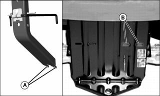
1. Fit tabs (A) on mounting post into slots (B) on rear hitch plate.
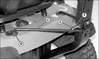
2. Insert bagger support rod (C) into the smaller holes in rear cargo mounts (D).
3. Install drilled cargo pin (E) into mounting post.
4. Install spring locking pin (F) into hole in drilled cargo pin.
Installing Bags
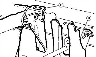
1. Install left and right bags (G) on mounting post (H).
NOTE: If hopper top will not seal properly, see Assembly Section - Adjust Hopper Top Latch for adjustment instructions.
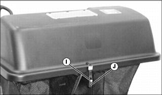
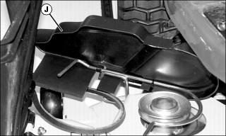
2. Close hopper top and fasten hood hold-down (I) over latch rod (J).
Installing POWER FLOW and Belt
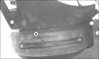
NOTE: Wear Strap Kit (A), is optional for mowing applications where contact with ground may cause external housing damage. Instructions included with Wear Strap Kit.
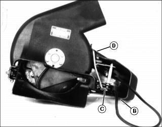
1. Pull on POWER FLOW belt loop (B) to release tension from POWER FLOW tension mechanism (C). Lever (D) must be free to rest on blower housing.
2. Apply a multi-purpose grease to mounting pin (E).
3. Route belt loop (B) towards double sheave and under plastic belt shield.
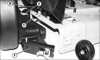
4. Swing front bracket (F) outward.
5. Slide mounting pin (E) in bracket hole (G) until POWER FLOW fits tight against deck.
6. Install front bracket (F) on welded bracket (H).
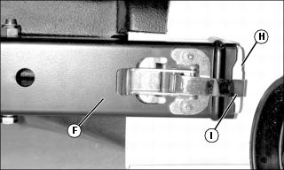
7. Latch bracket clamp (I) in welded bracket.
8. Raise plastic belt shield (J) to access double sheave.
IMPORTANT: Avoid damage! Belt must be under wire support on shield when shield is closed. Belt must be crossed as shown to prevent damage to shield. |
NOTE: Belt should not be under tension. If tension exists, repeat pulling of belt loop to release tension from POWER FLOW tension mechanism. Lever must be free to rest on blower housing.

Picture Note: For clarity, POWER FLOW cover and belt shield not shown in illustration.
9. Install POWER FLOW belt (K) on top sheave (L) of double sheave.
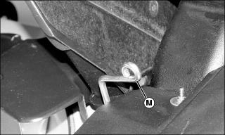
10. Pull lever (M) to rear to tighten belt.
NOTE: Chute latch (from chute bundle) fastens to POWER FLOW lever (M).
Installing Chute
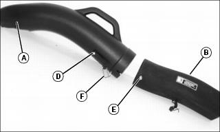
1. Insert upper chute assembly (A) into hopper top.
2. Slide lower chute assembly (B) over discharge opening in Power Flow assembly (C).
3. Slide bottom of upper chute over top of lower chute, aligning notch (D) with bolt (E).
4. Hook rubber strap latch (F) onto bolt (E) in lower chute.
IMPORTANT: Avoid damage! Machine damage can be caused by belt slipage. Lower chute latch must be attached to lever to maintain belt tension. |
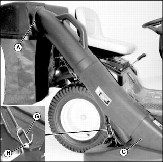
5. Connect lower chute latch (G) to lever (H) on blower assembly.


