
Service Transmission
Hydrostatic Transmission and Hydraulic Oil
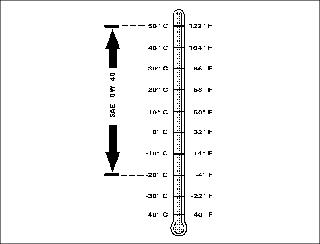
Use the following oil viscosity based on the air temperature range. Operating outside of the recommended oil air temperature range may cause premature hydrostatic transmission failure.
The following oil is recommended:
· JD Plus 50® 0W-40 Synthetic Blend
· API Service Classification SG or higher
Checking Hydraulic Oil Level
IMPORTANT: Avoid damage! Check oil level in reservoir tank when oil is cold. Do not overfill oil reservoir tank. Oil will expand during operation and could overflow. |
1. Park machine safely. (Refer to Parking Safely in SAFETY section.)
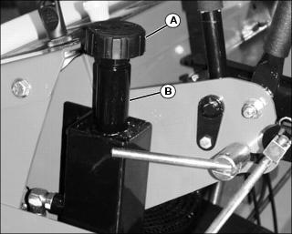
2. Clean area around reservoir dipstick cap (A).
3. Remove dipstick cap (A). Wipe dipstick clean.
NOTE: Do not tighten dipstick cap when checking oil level.
4. Insert dipstick into reservoir filler neck (B). Do not tighten cap.
5. Remove dipstick. Check oil level on dipstick. Oil level should be in crosshatch area between ADD and FULL marks.
· If oil is low, add oil to bring oil level no higher than FULL mark on dipstick.
· If oil is above FULL mark, drain oil to proper level.
6. Insert dipstick. Tighten cap.
Changing Hydraulic Oil and Filter
1. Park machine safely. (Refer to Parking Safely in the SAFETY section.)
2. Allow engine and hydraulic oil reservoir to cool.
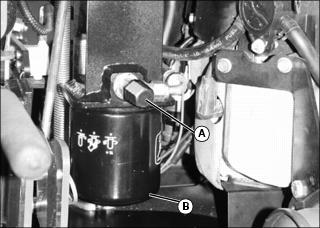
3. Turn metal cap (A) on bottom of hydraulic reservoir counterclockwise to remove.
4. Allow hydraulic oil to drain into a drain pan with a capacity of at least 3.8 L (1.0 gal).
5. Turn oil filter (B) counterclockwise to remove.
6. Apply a film of clean hydraulic oil to gasket of new filter.
7. Install new filter. Turn filter clockwise until gasket makes contact with mounting surface. Tighten 1/2 to 3/4 turn after gasket contact.
8. Clean area around reservoir dipstick cap.
9. Remove dipstick cap from hydraulic reservoir filler neck.
IMPORTANT: Avoid damage! Do not add oil beyond FULL mark. Oil capacity after draining may be less than dry fill capacity. Check oil level before filling completely. |
NOTE: Dry fill capacity for hydraulic system is 3.1 L (3.3 qt).
10. Fill oil reservoir with approximately 1.9 L (2 qt) of oil.
11. Insert dipstick. Tighten cap.
13. Move throttle lever to the fast position.
15. Cycle motion control levers forward and rearward several times. Check for leaks around filter.
16. Stop engine. Check oil level. Add oil as necessary to bring oil level to FULL mark on dipstick.
Cleaning Hydraulic Oil Pump Cooling Fins
IMPORTANT: Avoid damage! To ensure proper cooling, keep the cooling fins clean at all times. Operating the machine with obstructed cooling fins could cause damage due to overheating. |
1. Park machine safely. (See Parking Safely in the SAFETY section.)
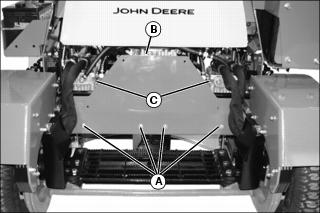
2. Remove four capscrews and washers (A).
3. Remove rear shield (B) to access hydraulic pumps (C).
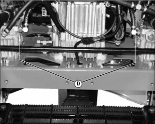
4. Clean hydraulic oil cooling fins (D) on each hydraulic pump with a rag, brush or compressed air.
5. Clean area around hydraulic pumps and frame.
Checking and Replacing Pump Traction Drive Belt
NOTE: The traction drive belt will not require a tension adjustment. Belt is self-adjusted using a spring tensioner.
Checking Traction Drive Belt
1. Park machine safely. (See Parking Safely in the SAFETY section.)
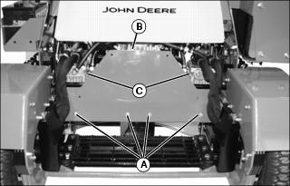
2. Remove four capscrews and washers (A).
3. Remove rear shield (B) to access hydraulic pumps (C).
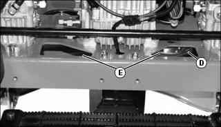
4. Inspect belt (D) through frame openings (E) for excessive wear, damage or stretching.
Removing Traction Drive Belt
1. Park machine safely. (See Parking Safely in the SAFETY section.)
2. Remove mower deck drive belt. See Replacing Mower Deck Drive Belt in the SERVICE MOWER section.
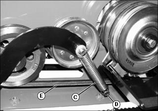
Picture Note: Traction drive belt tension spring, bottom view.
3. Disconnect drive belt tension spring (C) from anchor bolt (D).
4. Remove traction drive belt (E).
Installing Traction Drive Belt
NOTE: Install the traction drive belt (F) in front of anchor capscrew (I).
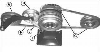
1. Install traction drive belt (F) on drive sheaves (G) and idler pulley (H) as shown. Ensure that traction drive belt is positioned in front of anchor capscrew (I).
2. Connect tension spring (J) to anchor capscrew (I).
Checking and Adjusting Motion Control Linkages
· If it is necessary to run an engine in an enclosed area, use an exhaust pipe extension to remove the fumes. |
NOTE: Check and adjust motion control linkages with the machine parked on a hard, level surface.
Checking Motion Control Linkages
1. Start the engine and run until it reaches normal operating temperature.
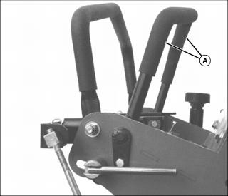
2. Stand on the operator's platform and, with the park brake released, move the motion control levers (A).
3. Observe wheel movement as motion control levers are moved back and forth. Wheels should travel in the correct direction as the levers are moved.
4. Move motion control levers to neutral position. If rear wheels continue to rotate, an adjustment is required.
Adjusting Motion Control Linkages
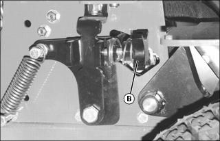
3. If rear wheels continue to rotate when motion control levers are in neutral, adjust neutral adjustment knob(s) (B) located on each side of machine.
· Turn adjustment knob (B) clockwise to stop forward rotation.
· Turn adjustment knob (B) counterclockwise to stop reverse rotation.
4. Check motion control linkages again. Continue to adjust knobs until there is no rotation of the rear wheels when the motion control levers are in the neutral position.
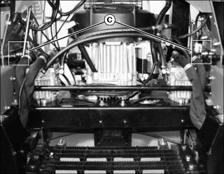
5. Check neutral positioning roller bearings (C).
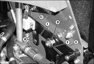
6. Adjust neutral positioning roller bearing (D) in slot of arm (E) so that roller bearing is seated in detent on pump arm (F).
7. Start the engine and operate the motion control levers.
· If machine will not turn over after adjustments are made, adjust the neutral switch (G). Loosen nuts and carriage bolts (H) and adjust switch contact bracket (I) up in slots. Tighten nuts.
· If neutral switch sensitivity needs to be increased, adjust switch contact bracket (I) down in slots.
Checking and Adjusting Transmission Tracking
· If it is necessary to run an engine in an enclosed area, use an exhaust pipe extension to remove the fumes. |
NOTE: Check and adjust transmission tracking with the machine parked on a hard, level surface.
Checking Transmission Tracking
1. Inflate tires to correct pressure.
2. Start engine and run until it reaches normal operating temperature.
3. Move machine to an open, level area for operation.
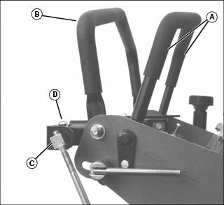
4. Drive machine forward, pushing both control levers (A) all the way to speed control bar (B).
5. If machine does not drive in a straight line, an adjustment is required.
Adjusting Transmission Tracking
1. Adjust appropriate control rod swivel (C) located on each side of machine.
· If machine tracks to the right, remove spring pin (D) and rotate left control rod swivel one turn clockwise. Install spring pin (D).
· If machine tracks to the left, remove spring pin (D) and rotate right control rod swivel one turn clockwise. Install spring pin (D).
2. Check transmission tracking again and adjust as required until machine drives in a straight line.
Adjusting Forward and Reverse Speeds
Adjusting forward speed:
1. Park machine safely. (See Parking Safely in the SAFETY section.)
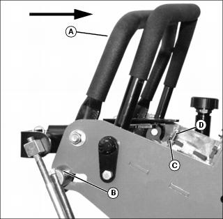
Picture Note: Arrow shows direction of speed control bar (A) movement when decreasing forward speed.
2. Loosen lock lever (B) on speed control bar (A) on each side of machine.
· To decrease forward speed, pull speed control bar (A) toward the operator's station.
· To increase forward speed, push speed control bar (A) forward (away from operator's station).
3. Tighten lock lever (B) on each side of machine.
Adjusting reverse speeds:
1. Park machine safely. (See Parking Safely in the SAFETY section.)
2. Loosen jam nut (C) on capscrew (D) on each side of machine.
· To decrease reverse speed, turn capscrew (D) counterclockwise.
· To increase reverse speed, turn capscrew (D) clockwise.
3. Tighten jam nut (C) on capscrew (D) on each side of machine.