
Service Transmission
Transmission and Hydraulic Oil
NOTE: Greensmower is filled with John Deere HY-GARD® (J20C) Transmission and Hydraulic Oil at the factory. DO NOT mix oils. DO NOT use type "F" automatic transmission fluid or J20D Low Viscosity HY-GARD®.
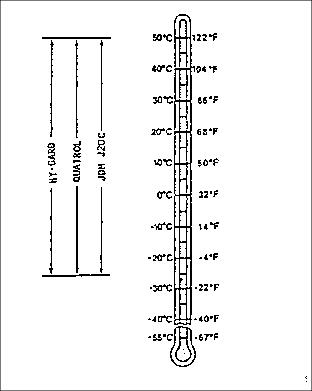
Use oil viscosity based on the expected air temperature range during the period between oil changes.
John Deere HY-GARD® Transmission/Hydraulic Oil is recommended.
Other oils may be used if they are QUATROL® oils or if they meet John Deere Standard JDM J20C.
Adjusting Transmission Neutral
NOTE: The greensmower may creep forward or backward while in neutral position with engine running. If so, an adjustment is needed.
Check Transmission Neutral Adjustment
2. Unlock the park brake with transmission in neutral.
3. Adjust the neutral return mechanism if the machine moves. Adjust until greensmower does not move while the machine is in neutral position.
Transmission Neutral Adjustment
1. Park the machine safely. (See Parking Safely in the SAFETY section.)
2. Move mow/transport lever to the transport position.
3. Secure operator seat in the raised position.
4. Use safe lifting device to lift front of greensmower so drive wheels are off the ground. Support with jack stands or wooden blocks.
6. Adjust throttle level to slow idle.
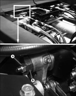
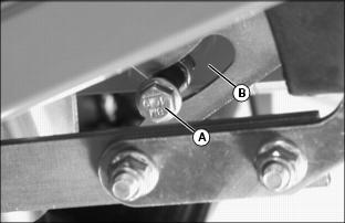
8. Loosen eccentric jam nut (A).
9. Slowly turn eccentric cam (B) clockwise or counterclockwise to stop any drive wheel rotation.
10. Hold eccentric cam and tighten eccentric jam nut.
· Depress and release forward and reverse travel pedals.
· Check turning motion of drive wheels when transmission is in neutral.
· Repeat adjustment until the wheels do not turn when the transmission is in neutral.
NOTE: The neutral lock adjustment should be done after the transmission neutral adjustment.
Adjusting Neutral Lock
NOTE: . Transmission neutral adjustment must be completed prior to doing this service adjustment.
Check Position of Neutral Lock Pin
1. Locate neutral lock linkage under the right side of the operator platform.
2. Depress and lock park brake pedal in the first engaged position.
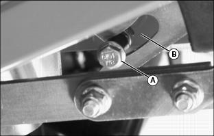
· The neutral lock pin (A) should be engaged into the narrow opening of slot (B) in the forward travel pedal linkage.
· When the park brake is unlocked, the neutral lock pin (A) should be in the wide opening of slot (B). The forward travel pedal should have full forward and full reverse motion within the pedal linkage opening.
4. Adjust the neutral lock if both of these conditions are not met.
Adjust Position of Neutral Lock Pin
1. Locate neutral lock adjustment mechanism under the right side of the operator platform.
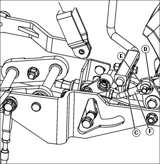
2. Loosen jam nut (C) on the neutral lock rod.
3. Remove cotter pin (D) and flat washer (E) from the neutral lock driver arm.
4. Disconnect rod end (F) off of driver arm.
6. Install rod end (F), flat washer (E) and cotter pin (D) onto driver arm.
8. Check neutral lock pin engagement.
Checking and Adjusting Park Brake Neutral
Check Adjustment
1. Depress and lock park brake pedal in the first engaged position.
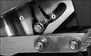
· The neutral lock pin (A) should be engaged into the narrow opening of slot (B) in the forward travel pedal linkage.
· The forward travel pedal should not move or should lift up slightly when the brake is engaged.
3. Check drive wheels for movement.
· If the drive wheels begin to creep when the brake is set, adjustment is required.
Adjust Park Brake Neutral
2. Use safe lifting device to lift front of greensmower so drive wheels are off the ground. Support with jack stands or wooden blocks.
3. Secure operator seat in the raised position.
4. Depress and lock park brake in the first engaged position.
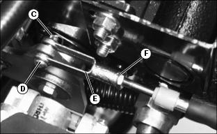
5. Remove cotter pin (C) and clevis pin (D) connecting the cable linkage yoke (E) to the hydraulic pump lever.
9. Check drive wheel movement.
· If the drive wheels begin to creep with the brake pedal locked in the first engaged position, additional adjustment is necessary. Continue adjustment process until creep is gone.