
Service Cutting Units
Avoid Injury From Contacting Blades
Removing and Installing Cutting Units
Removing Cutting Units
1. Park the machine safely. (See Parking Safely in the SAFETY section.)
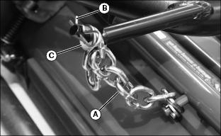
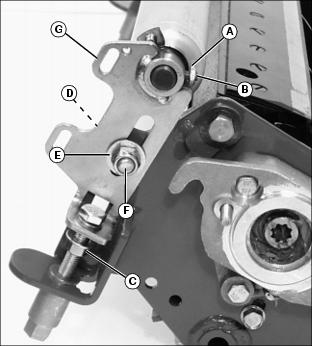
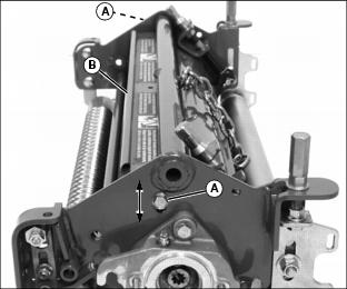
NOTE: Identify which chain link is installed to the lift arm so lift chain can be installed correctly.
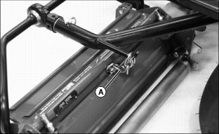
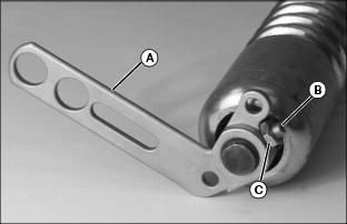
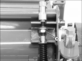
2. Disconnect lift chains (A) from lift arms.

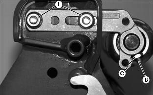
· Remove spring locking pin (B) and flat washer (C).
· Remove chain from lift arm pin.

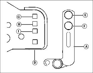
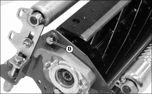
3. Disconnect yoke (D) from lift arm (E).
· Roll cutting unit forward away from lift arm.
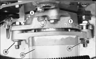
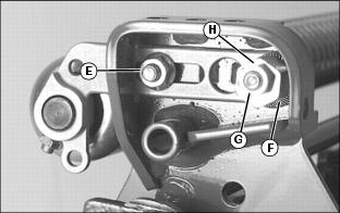
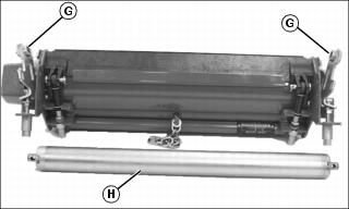
4. Remove hydraulic motor (G).
· Loosen locking assembly hardware (H).
· Rotate motor from reel bearing housing slots (I).
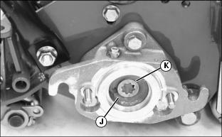
5. Inspect inside of reel bearing housing (J) for grease. Add John Deere Special Purpose HD Cornhead Grease to housing if additional lubrication is needed.
6. Check splined motor/reel coupling (K) for wear. Replace if necessary. Make sure coupling is lubricated with grease and remains in position on reel shaft.
7. Repeat procedure for other cutting units if necessary.
Installing Cutting Units
NOTE: Center cutting unit has the upstop bracket. Right front cutting unit has the steering limiter bracket.

1. Install hydraulic motor (G) onto the reel bearing housing.
· Align splined reel coupling with splined motor drive shaft.
· Align locking assembly hardware with reel bearing housing slots (I).
· Tighten assembly lock nuts (H).
NOTE: Yoke with steering limiter bracket must be installed to the right front lift arm.
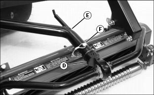
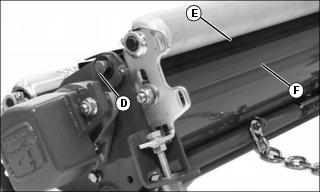
2. Install yoke (D) to lift arm (E).
3. Align yoke pin and lift arm mounting holes.
4. Fasten cutting reel in position with quick-lock pin (F).
NOTE: The lift chain can be installed to different links to adjust cutting unit lift height.
5. Install lift chain (A) onto lift arm pin. Make sure chain is not kinked.
6. Install flat washer (C) and spring locking pin (B).
7. Repeat procedure for other cutting units if necessary.
Removing Cutting Unit Yokes
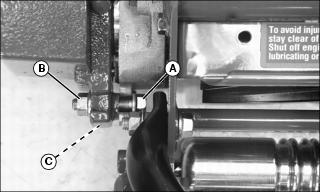
1. Remove flange head bolt (A), lock nut (B) and two pivot bushings (C) from each end of cutting unit yoke.
2. Install in reverse order of removal.
Removing and Installing Front Roller
Removing Front Roller
1. Remove cutting unit from greensmower.
2. Position cutting unit upright on a flat surface or workbench.
3. Remove hardware from left roller bracket.
· Remove flange nut (A) and carriage bolt.
· Remove lock nut (B), eccentric adjuster (C), serrated washer (D) and carriage bolt.
4. Remove hardware from right roller bracket.
· Remove flange nuts (E) and carriage bolts.
5. Remove roller and bracket assembly from cutting unit frame.

6. Loosen jam nut (F) and set screw (G) to remove bracket (H) from each bearing spindle shaft end.
Installing Front Roller
NOTE: Roller brackets are offset. For standard use, the bracket should be installed to the roller with the offset to the rear of the base cutting unit to allow close proximity of front roller to rear roller. If GTC is being installed, offset should be to the front to allow the GTC to be installed behind the front roller.
Install the roller bracket with the larger holes and adjustment slot on the left side of the cutting unit.
The roller bearing spindle shaft has holes drilled in each end. Do not tighten set screws near the holes.
Picture Note: Photo shows left roller bracket being installed.
1. Install roller brackets (A) onto each bearing spindle shaft end.
2. Install set screws (B) and jam nuts (C) loosely. Do not tighten.
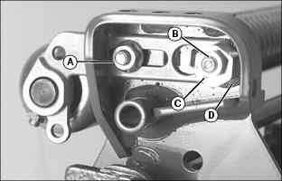
3. Select Height-of-Cut (HOC) adjustment range.
· Alignment of roller bracket (A) and cutting unit frame (D) adjustment holes will determine HOC adjustment range.
· Refer to chart for desired setting.
0-6.531 |
|||
1
This setting is used when the diameter of the cutting reel has worn down to 120mm (4.7 in.) or less. |
4. Slide assembly roller brackets into cutting unit frame slots.
5. Align selected HOC adjustment holes.
NOTE: Install carriage bolts from the inside.
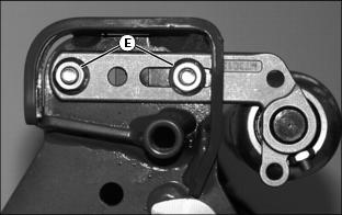
6. Fasten bottom of left roller bracket to frame using one M8x20 carriage bolt and one M8 flange nut (E).
NOTE: Install serrated washer with cupped side facing cutting unit frame.
7. Fasten top of left roller bracket to frame using one M8x40 carriage bolt, one serrated washer (F), one eccentric adjuster (G) and one M8 lock nut (H).
8. Fasten right roller bracket to frame using two M8x20 carriage bolts and two M8 flange nuts (I).
NOTE: Make sure the roller bracket set screw locations are not aligned with the holes in each bearing spindle shaft end. Set screws must engage the bearing spindle shaft at each end.
9. Center front roller. Tighten set screws (B) and jam nuts (C) on both roller brackets.
10. Tighten roller bracket attaching hardware.
11. Adjust front roller for parallelism.
Removing and Installing Rear Roller
Removing Rear Roller
1. Remove cutting unit from greensmower.
2. Position cutting unit with bottom side up on a flat surface or workbench.
3. On each side of rear roller, loosen jam nut (A) and set screw (B).
4. Loosen jam nut (C) on each adjuster tower.
5. Remove carriage bolt (D), flat washer (E) and lock nut (F) attaching each height-of-cut (HOC) adjustment bracket (G) to the cutting unit frame.
6. Move height-of-cut (HOC) brackets (G) away from each bearing spindle shaft end.
Installing Rear Roller

1. Install roller bearing spindle shafts (A) into each height-of-cut (HOC) bracket (B).
2. Install both height-of-cut brackets to cutting unit frame.
NOTE: Install carriage bolts from the inside.
3. Install carriage bolt (C), flat washer (D) and lock nut (E).
5. Center rear roller (F) inside HOC brackets.
6. Tighten set screws (G) and jam nuts (H).
7. Loosen lock nuts (E) approximately 1/4 turn.
8. Tighten jam nut (I) on each adjuster tower.
Replacing Bed Knife
Removing Bed Knife
1. Remove the cutting unit from greensmower.
2. Position cutting unit with the bottom side down on a flat surface or workbench.
3. Relieve tension from bed knife tension springs on both sides of cutting unit.
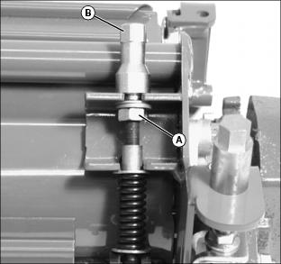
· Turn jam nuts (A) counterclockwise until springs are completely compressed.
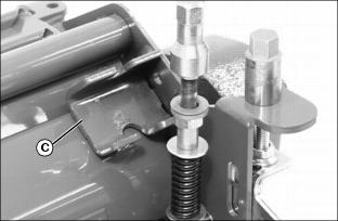
5. Rotate each adjustment assembly away from reel housing bracket (C).
6. Rotate cutting unit and position with bottom side up on flat surface or workbench as shown.
7. Remove shoulder bolt (D) from each end of cutting unit.
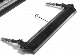
8. Slide bed knife assembly (E) out of the cutting unit housing.
9. If original bed knife is to be used again, grind the bedknife. (See Grinding the Bed Knife in this section.)
Installing Bed Knife
1. Remove and discard thirteen screws attaching bed knife to assembly support. Discard bed knife.
NOTE: Remove debris, corrosion, and rust from bottom surface of bed knife support.
2. Install bed knife using new screws. Alternate tightening by starting with center screws and working out to the ends. Tighten screws to 7 N·m (62 lb-in).
3. If installing a used bed knife, grind the bed knife. (See Grinding the Bed Knife in this section.)
4. Slide bed knife and support assembly (E) into position inside locator shoe (F).
5. Install both shoulder bolts (D). Tighten hardware to 55 N·m (40 lb-ft).
6. Position cutting unit with bottom side down on flat surface or workbench.
7. Install each adjustment assembly inside housing mounting bracket.
· Restore bed knife spring tension by turning jam nuts (A) clockwise. Turn jam nuts only midway up the threaded adjustment.
11. Check height-of-cut and adjust as necessary.
Grinding the Bed Knife
NOTE: Bed knife and support assembly must be ground as a complete unit.
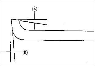
1. When grinding the bed knife, it is important to have a 6.5° relief angle on the top surface (A) and a 5° relief angle on the front surface (B).
2. Put entire bed knife support and bed knife in a suitable grinder and grind until material is consistently removed from the entire length of the top and front surfaces of the bed knife.
Adjusting Cutting Unit Shield
NOTE: Keeping the shield close to the cutting blades improves the performance of the grass catcher in most conditions.
1. Loosen two bolts (A) and lock nuts on each side of cutting unit.
2. Raise or lower shield (B) to desired position.
· Maintain an approximate 1.5mm (0.06 in.) clearance between the bottom of the shield and the top of the cutting blades.
Backlapping Cutting Units
Avoid injury from rotating blades. Keep hands and feet away while greensmower is running. |
NOTE: To help maintain sharp edges required on cutting reels, bed knife-to-reel clearance should be checked before the backlapping function begins. The bed knife must be adjusted properly to ensure light, even contact over the length of the cutting blades.
Cutting reels are all backlapped at the same time.
1. Check bed knife-to-reel clearance on all three cutting reels. Adjust if necessary.
3. Move mow/transport lever to the TRANSPORT position.
5. Lower cutting units to the ground.
NOTE: Operator must be off the seat for the backlapping valve to function.
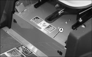
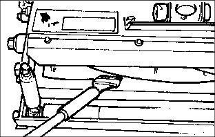
7. Open service access panel (A) below operator seat platform.
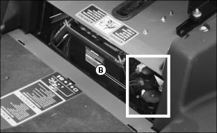
8. Locate backlapping valve (B) to the left of the battery.
· Position throttle lever between mid-range and SLOW idle.
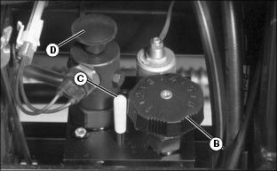
· Turn reel speed control knob (B) clockwise until indicator (C) is aligned with a number between "1" and "3".
NOTE: Forward/Reverse control knob must be pulled up completely past first detent for the backlapping valve to function properly.
· Pull Forward/Reverse control knob (D) UP until a click is heard.
12. Move the Mow/Transport lever to MOW position.
13. Activate Raise/Lower lever.
· Move and hold lever forward.
· When cutting reels begin turning in REVERSE, release lever.
NOTE: Adjust reel speed slow enough so reel sharpening compound is not thrown off during the backlapping procedure.
14. Using a Long handled brush, carefully apply reel sharpening compound, uniformly, from one end of the cutting reel to the other. Repeat application in opposite direction. Allow cutting reel to continue running backwards until reel is quiet.
15. Periodically disengage cutting units by moving the Mow/Transport lever to the TRANSPORT position and turn key switch to the "STOP" position. Visually check blade appearance.
NOTE: Forward/Reverse control knob must be pushed down to restart engine.
· Check for uniform clearance across entire bed knife. If clearance is not uniform, repeat backlapping procedure until clearance is uniform across entire bed knife.
IMPORTANT: Avoid damage! Do not operate cutting reels in the forward direction until reel sharpening compound is washed from the unit. Unless properly washed, the reels can be dulled by the compound. |
16. Use water to thoroughly wash off all reel sharpening compound while cutting reels are turning in reverse.
17. Move Mow/Transport lever to the TRANSPORT position.