
Service Electrical
Battery Statement
Service the Battery Safely

Removing and Installing Battery
IMPORTANT: Avoid damage! The battery drain tube allows excess battery acid to flow away from the machine. Make sure the tube opening is free of obstruction. |
Removing:
1. Park the machine safely. (See Parking Safely in the SAFETY section.)
2. Secure the operator seat in the raised position.
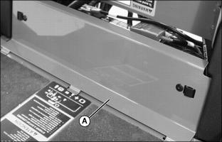
3. Remove service access panel (A) below operator seat platform.
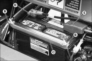
4. Loosen wing nuts (B) to remove battery hold-down (C).
5. Disconnect negative (-) battery cable (D).
6. Push red cover away from positive (+) battery cable (E) and disconnect cable from battery.
Installing:
1. Install battery into vehicle.
2. Check cell caps to be sure vent holes are open.
3. Connect positive (+) cable to battery first, then negative (-) cable.
4. Apply petroleum jelly on battery terminals to help prevent corrosion.
5. Install battery hold-down. Tighten wing nuts.
6. Install service access panel.
Checking Battery Electrolyte Level (Maintenance-Type Battery)
NOTE: Add only distilled water to replace normal electrolyte loss.
1. Park the machine safely. (See Parking Safely in the SAFETY section.)
2. Remove battery from machine and set it on a level surface.
3. Remove battery cell caps. Make sure cap vents are not plugged.
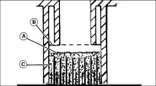
4. Check electrolyte level. Electrolyte (A) should be approximately halfway between bottom of filler neck (B) and top of plates (C).
IMPORTANT: Avoid damage! Do not overfill battery. Electrolyte can overflow when battery is charged and cause damage. |
5. Add only distilled water if necessary.
Cleaning Battery and Terminals
1. Park machine safely. (See Parking Safely in the SAFETY section.)
2. Disconnect and remove battery.
3. Wash battery with solution of four tablespoons of baking soda to one gallon of water. Be careful not to get the soda solution into the cells.
4. Rinse the battery with plain water and dry.
5. Clean terminals and battery cable ends with wire brush until bright.
6. Apply petroleum jelly or silicone spray to terminal to prevent corrosion.
Using Booster Battery
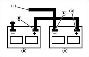
1. Connect positive (+) booster cable to booster battery (A) positive (+) post (C).
2. Connect the other end of positive (+) booster cable to the disabled vehicle battery (B) positive (+) post (D).
3. Connect negative (-) booster cable to booster battery negative (-) post (E).
4. Connect the other end (F) of negative (-) booster cable to a metal part of the disabled machine frame away from battery.
5. Start the engine of the disabled machine and run machine for several minutes.
6. Carefully disconnect the booster cables in the exact reverse order: negative cable first and then the positive cable.
Checking Electrical Control Box
The electrical control box is a diagnostic tool to help the operator verify correct electrical functions of the greensmower. For the control box to function correctly, all input switches, output solenoids and relays must be connected and functioning properly.
1. Park the machine safely. (See Parking Safely in the SAFETY section.)
2. Turn the key to the RUN position.
3. Secure operator seat in the raised position.
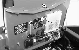
4. Locate electrical control box (A).
NOTE: The control box is equipped with a diagnostic light which indicates if the control box is functioning correctly. When the control box is functioning correctly, the diagnostic "HEARTBEAT" light (B) will be illuminated and blinking whenever the key switch is turned to the RUN position.
5. Check to see if the diagnostic "HEARTBEAT" light is blinking.
· Check to see if battery is charged. Charge if needed.
· Blown 15 amp key switch fuse (C).
· Electrical harness connections.
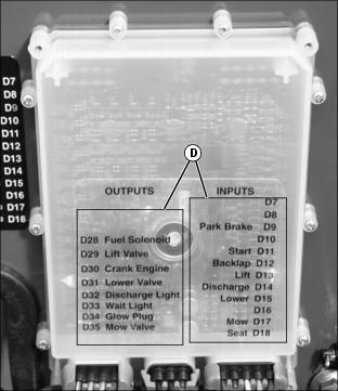
7. Use the control box display lights (D) to diagnose the problem. The control box will light as each function switch is actuated.
8. If further diagnostic assistance is needed, refer to the Technical Manual or consult your John Deere distributor.
Checking and Replacing Fuse
IMPORTANT: Avoid damage! The electrical system may be damaged if incorrect replacement fuses are used. Replace the bad fuse with a fuse of the same amp rating. |
1. Park the machine safely. (See Parking Safely in the SAFETY section.)
2. Secure operator seat in the raised position.
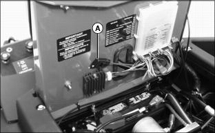
3. Locate fuse holder (A) under operator seat platform.
5. Check fuse visually for a broken filament.
Replacing Engine Indicator Light Bulb
1. Park the machine safely. (See Parking Safely in the SAFETY section.)
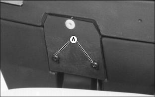
2. Remove two screws (A) from left side of console control armrest.
3. Secure operator seat in the raised position.
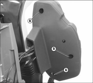
4. Loosen and remove cap screws and flat washers from locations (B) in bottom of console control armrest.
5. Carefully separate upper and lower console control armrest halves.
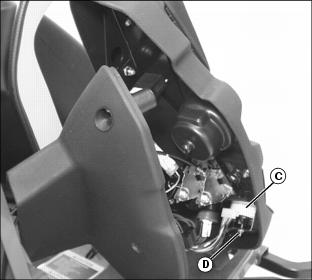
6. Locate engine indicator light assembly (C).
NOTE: It may be necessary to remove hardware (D) and retainer bracket to access all engine indicator light bulb sockets.
7. Turn light bulb socket counterclockwise to remove.
10. Install socket and turn clockwise to secure in position.
11. Carefully assemble upper and lower console control armrest halves.
12. Install cap screws and flat washers into bottom of console control armrest locations. Do not tighten.
13. Install two screws into left side of console control armrest.