
Assembly
Identify Parts
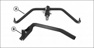
A - Cutting Unit Yoke (3 shipped)
Bag of Parts List
Check Tire Pressure
2. Check tire pressure with an accurate gauge.
3. Add or remove air, if necessary.
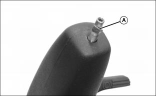
Install Rear Wheel Assembly
1. Cut steel bands securing rear steering wheel hub assembly to the shipping pallet.
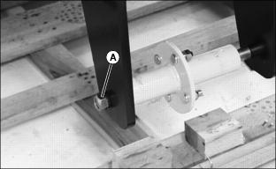
2. Remove hex nut (A) securing wheel hub assembly to rear yoke.
3. Lift rear of greensmower with a safe lifting device.
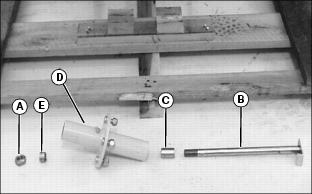
4. Remove axle (B), bushing (C), hub assembly (D) and bushing (E) from yoke.
5. Inflate rear tire to 69-83 kPa (10-12 psi).
6. Remove wheel nuts from the hub assembly.
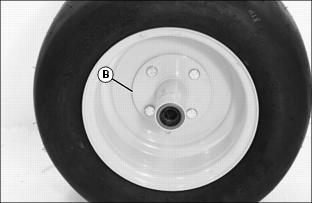
7. Install hub (D) onto wheel with wheel nuts. Tighten nuts alternately to 81-95 N·m (60-70 lb-ft).
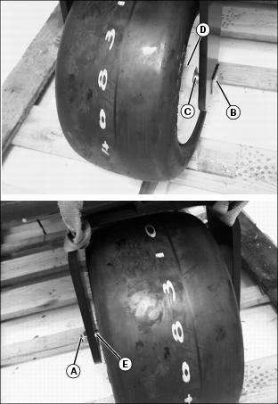
8. Install axle (B) through right side of yoke, bushing (C), hub assembly (D), bushing (E) and left side of yoke.
9. Fasten wheel to yoke with hex nut (A). Tighten hex nut to eliminate motion side-to-side, but do not overtighten. Wheel must rotate freely.
10. Lower rear of greensmower.
11. Lubricate steering wheel axle bearings with John Deere Multi-Purpose HD Lithium Complex Grease or equivalent.
Install Front Wheels
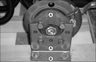
1. Loosen four wheel bolts (A) in each front drive wheel hub.
2. Remove cap screws (B) and lock nuts securing shipping brackets to shipping crate base.
3. Raise front of greensmower with a safe lifting device.
4. Remove wheel bolts and shipping brackets from each front drive wheel hub. Discard both shipping brackets.
5. Inflate drive tires to 69-83 kPa (10-12 psi).
NOTE: Make sure each drive wheel valve stem faces to the outside.
6. Install drive wheels using four wheel bolts. Tighten until snug.
7. Lower front of greensmower.
8. Tighten wheel bolts alternately to 81-95 N·m (60-70 lb-ft).
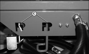
9. Install front cutting reel motors into "R" shaped holes (C) stamped in the front of the operator platform.
10. Lay the center cutting reel motor inside the fuel tank tray.
11. Carefully move greensmower off shipping crate base.
Install Operator Seat
NOTE: For maximum operator comfort, use forward seat pan mounting holes when installing the seat.
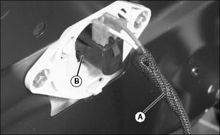
1. Connect wire harness (A) to safety switch (B) located under operator seat.
2. Install rear of seat onto slide rail studs (C) and fasten with two 5/16 in. flanged lock nuts (D). Do not tighten.
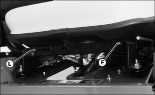
3. Fasten front of seat to slide rail assembly with two 5/16 in.x5/8 in. hex bolts (E).
Install Steering Wheel
1. Coat splined steering wheel shaft (A) with multi-purpose grease.
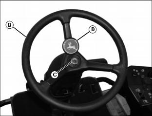
2. Position rear wheel straight and facing forward.
3. Install steering wheel (B) onto the shaft.
4. Install 5/8 in. hex nut (C) and tighten until snug.
Check and Connect the Battery
· Wear eye protection and gloves. · Do not allow direct metal contact across battery posts. |
1. Move operator seat rearward as far as possible.
2. Secure operator seat in the raised position.
3. Check battery electrolyte level.
· If the voltage is below 11.6 volts, charge the battery.
5. Connect red positive (+) cable to battery. Apply petroleum jelly or silicone spray to terminal to prevent corrosion. Make sure connection is tight. Install the red terminal cover.
6. Connect black negative (-) cable to battery. Apply petroleum jelly or silicone spray to terminal to prevent corrosion. Make sure connection is tight.
Install Left Yoke Stop Arm
Install yoke stop arm (A) to greensmower foot platform with two M8 x 50 carriage bolts (B) and two M8 flanged hex lock nuts.
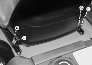
Install Operator Protective Device
1. Lift seat to upright position.
NOTE: The tube assembly should be installed so the top of the assembly curves toward the rear of the machine.
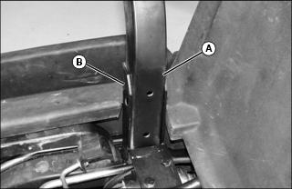
2. Place the ends of the tube assembly (A) inside the right and left pre-drilled mounting brackets (B) on the greensmower.
NOTE: Cap screws should be installed so nuts are installed to the inside (D) and rear (C) of the bracket.
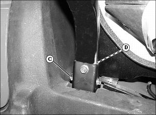
3. Install cap screws through holes on both right and left side of the mounting brackets. Install nuts.
4. Tighten the upper nut on each side first, and then the lower nuts. Tighten to 50 N·m (37 lb-ft).
Assemble Cutting Units
The Model 2500A Greensmower is shipped from the factory without the cutting units installed. The hydraulic reel motors and cutting reel yokes are shipped with the greensmower.
Refer to installation instructions packaged with the cutting units when installing the cutting units and cutting unit yokes onto the greensmower. Retain these instructions with the operator's manual for future reference.
Hardware used to install the cutting units and cutting unit yokes onto the greensmower is included in the greensmower parts bag. Hardware must be retained for cutting unit and cutting unit yoke assembly procedures.
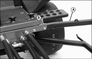
Check and Adjust Lift Arm Stops
NOTE: Lift arm stop adjustment must be performed at initial set-up and when changing tire sizes.
Check Adjustment
1. Turn key switch to the RUN position.
2. Push Raise/Lower lever FORWARD to relieve hydraulic pressure in the front and center lift arm cylinders.
3. Push down front and center lift arms.
4. Turn key switch to the STOP position.
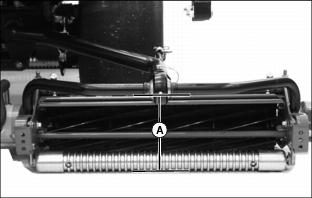
5. Measure distance (A) between the center of each yoke ball joint and the ground.
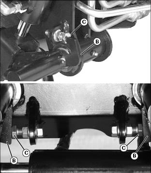
· All three yoke ball joints should be approximately 225mm (8-7/8 in.) above the ground with the lift arm down stop plates (B) contacting the stop bolts (C).
Adjust Lift Arm Stops

1. Measure distance (A) between the center of each yoke ball joint and the ground.
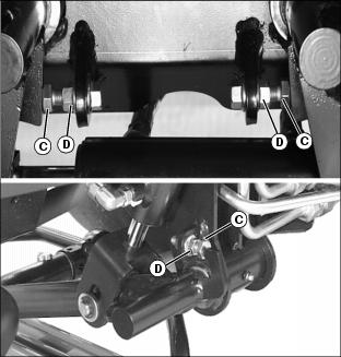
Picture Note: Top photo shows front cutting unit lift arm stop adjustments. Bottom photo shows center cutting unit lift arm stop adjustment.
2. Loosen stop bolt jam nuts (D).
3. Adjust the stop bolts (C) as needed until all three yoke ball joints are 220-230mm (8.7-9.1 in.) above the ground.
Check Fluid Levels
NOTE: Refer to the Service sections of the operator manual for information concerning check locations and proper fluid levels.
1. Check radiator coolant level.
Check Machine Safety System
Perform safety system check to make sure the electronic safety interlock circuit is functioning properly.