
Operating - Machine
Daily Operating Checklist
Avoid Damage to Plastic and Painted Surfaces
· Do not wipe plastic parts unless rinsed first.
· Insect repellent spray may damage plastic and painted surfaces. Do not spray insect repellent near machine.
· Be careful not to spill fuel on machine. Fuel may damage surface. Wipe up spilled fuel immediately.
Pedestal Controls
A - Tilt Steering Adjustment Handle
Console Controls
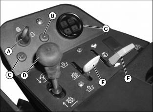
B - Glow Plug Indicator Light (Diesel Model)
G - Leak Detector Indicator Light (Optional)
Foot Platform Controls
A - Park Brake Pedal/Emergency Brake
Miscellaneous Controls
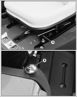
Adjusting Operator Seat
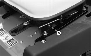
1. Sit on the seat and pull lever (A) to the left.
2. Slide seat forward or backward to desired position.
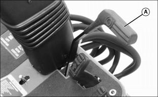
Adjusting Tilt Steering Wheel
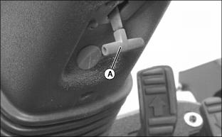
1. Raise and hold adjustment T-handle (A).
2. Move steering wheel to desirable operating position.
3. Lower T-handle to lock steering wheel in position.
Adjusting Mowing Speed
NOTE: Greensmower is preset at the factory to operate at approximately 7.1 km/h (4.4 mph).
Wheel RPM's necessary to meet the preset mow speed specification are 168 to 192. Wheel RPM's have been preset at the factory to assure proper forward mow speed regardless of tire size.
1. Park the machine safely. (See Parking Safely in the SAFETY section.)
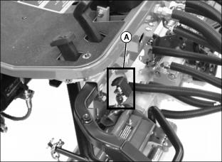
2. Locate mow speed adjustment (A).
3. Move Mow/Transport lever to the MOW position.
NOTE: Preliminary dimension (B) between top of mow speed adjustment and bottom of forward travel pedal linkage is 22mm (0.87 in.) When mow speed adjustments change, record any dimension (B) changes for future reference.
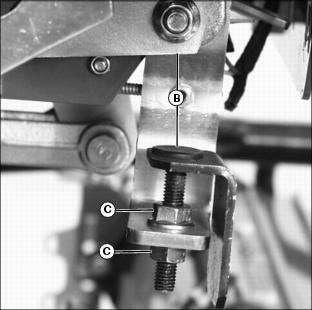
· Increase dimension (B) for increased mowing speed.
· Decrease dimension (B) for decreased mowing speed.
7. Move Mow/Transport lever to the TRANSPORT position.
8. Measure off 30.5 m (100 ft.)
10. Move Mow/Transport lever to the MOW position.
11. Move throttle lever to the FAST position. Depress FORWARD travel pedal fully.
12. Record the number of seconds it takes to travel the 30.5 m (100 ft.) length.
13. Refer to applicable cutting ratio table to determine ground speed and frequency of cut.
14. Continue adjustment process until desired mowing speed and frequency of cut is achieved.
Cutting Ratios
Testing Safety Systems
The safety systems installed on your machine should be checked before each machine use. Be sure you have read the machine operator manual and are completely familiar with the operation of the machine before performing these safety system checks.
Use the following checkout procedures to check for normal operation of machine.
If there is a malfunction during one of these procedures, do not operate machine. See your authorized dealer for service.
Perform these tests in a clear open area. Keep bystanders away.
Testing Mow-Transport Lever Switch
Test 1
3. Put transmission in NEUTRAL.
4. Move Mow/Transport lever to the MOW position.
5. Turn key switch to the START position.
NOTE: Move Mow/Transport lever to the TRANSPORT position and turn the key to the STOP position before starting engine.
Test 2
3. Put transmission in NEUTRAL.
6. Lower cutting units to the ground.
7. Move Mow/Transport lever to the MOW position.
Testing Raise/Lower Lever Switch
3. Move Mow/Transport lever to the TRANSPORT position.
6. Put the transmission in neutral.
7. Lower cutting units with the Raise/Lower lever.
8. Move Mow/Transport lever to the MOW position.
Testing Seat Switch
Test 1
3. Move Mow/Transport lever to the TRANSPORT position.
6. Put transmission in neutral.
7. Move Mow/Transport lever to the MOW position.
8. Push the Raise/Lower lever forward. Cutting reels should start rotating.
Test 2
5. Put the transmission in neutral.
6. Move Mow/Transport lever to the TRANSPORT position.
Using Park Brake
Locking The Park Brake:
1. Push and hold brake pedal (A) down.
2. Push park brake lock (B) down.
4. Release park brake lock. Brake pedal should stay down and park brake lock should stay locked.
Unlocking The Park Brake:
1. Push brake pedal (A) down. Park brake lock (B) should release immediately.
Glow Plug
NOTE: Glow plugs preheat the combustion chamber for better starting performance.
1. Turn key switch to the RUN position.
· The amber glow plug indicator light (A) should go on.
· The indicator light should go off in approximately three seconds after the key switch is turned to the RUN position.
2. Turn the key switch to the START position to start the engine.
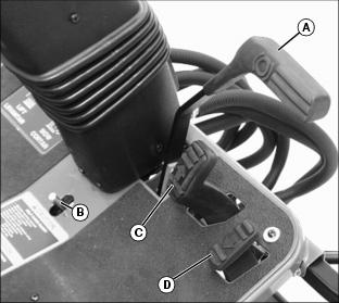
Using the Raise/Lower Lever
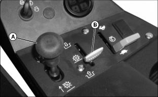
1. Push Raise/Lower lever (A) forward to lower cutting reels.
· If the Mow/Transport lever (B) is in the MOW position, the cutting reels will begin to rotate.
· If the Mow/Transport lever is in the TRANSPORT position, the cutting units will lower but the reels will not rotate.
2. Pull lever (A) rearward to raise cutting units.
· If the Mow/Transport lever is in the MOW position, the cutting reels will stop rotating.
Using the Mow/Transport Lever
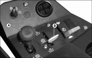
1. Pull the Raise/Lower lever (A) rearward to raise cutting units.
2. Move the Mow/Transport lever (B) to the MOW position.
3. Push the Raise/Lower lever forward to lower cutting units.
· Cutting reels will begin to rotate as the cutting units are lowered.
4. Pull Raise/Lower lever rearward to raise cutting units.
· Cutting reels will stop rotating as the cutting units are raised.
5. Move the Mow/Transport lever to the TRANSPORT position to disengage reel drive for cutting units.
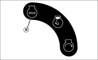
Using the Key Switch
NOTE: To help prevent engine backfiring, the engine will continue to run approximately two seconds after key switch is turned to the "STOP" position. After engine has stopped, an approximate two-second delay will prevent the engine from immediately being restarted.
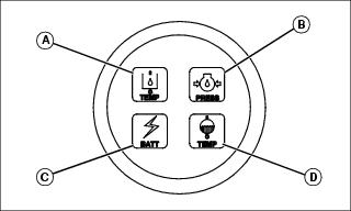
Key Switch (A) Positions:
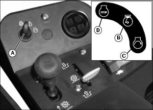
· RUN position (B)-the engine oil pressure indicator light and battery indicator light should come on. Engine is ready to start. If the machine is equipped with an optional leak detector indicator system, the leak detection light will glow and an alarm will sound momentarily.
· START position (C)-start engine.
· STOP position (D)-shut engine off.
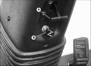
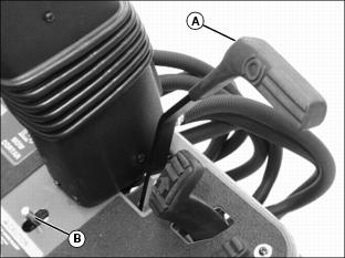
Using Fuel Shut-Off Valve (Diesel Model)
2. Locate fuel filter sediment bowl assembly on the left side of the engine.
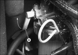
Picture Note: Fuel shut-off valve shown in the open position.
3. Rotate fuel shut-off valve lever (A) to the "O" (open) position or "C" (closed) position.
"C" (Closed) Position:
· When performing any type of engine service.
· During periods of extended storage.
"O" (Open) Position:
· Fuel shut-off valve must be in the full OPEN position for proper fuel delivery to the engine.
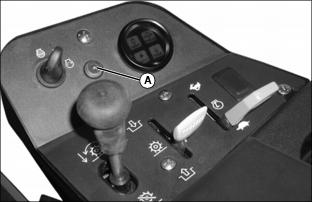
Using the Hour Meter
NOTE: The hour meter, located under the console armrest, will run when key switch is in the RUN position.
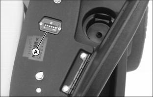
· The hour meter (A) shows the approximate number of hours the greensmower has run.
· Use the hour meter and Service Interval Chart to determine when the greensmower will need service.
Indicator Lights
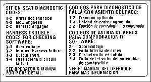
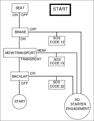
Using Sit-On-Seat (SOS) Indicator Light Diagnostics
Sit-On-Seat (SOS) indicator light diagnostics are provided to help diagnose problems starting the greensmower.
The following conditions must be met to energize the starter solenoid and engage the starter motor:
· Mow/Transport lever in TRANSPORT position.
· Backlap valve in off position.
· Key switch in the START position.
NOTE: Sit-on-seat diagnostic code label is located under console armrest.
Ignition Interlock Systems
The following conditions must be met for the starter to engage:
· Operator can be on or off the seat.
· Mow/Transport lever in the TRANSPORT position.
· Backlap valve in OFF position.
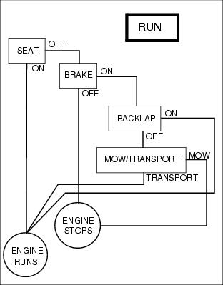
The following condition must be met for the engine to run:
· Operator must be on the seat or the park brake must be locked.
If the Mow/Transport lever is in the TRANSPORT position with the park brake unlocked and the operator rises off the seat, the engine will stop.
If the Mow/Transport lever is in the MOW position with the park brake locked and the operator raises off the seat, the engine will stop.
If the cutting reels are rotating and the operator raises off the seat, the cutting reels and engine will stop.
The following conditions must be met in order to mow:
· Operator in the operator seat.
· Throttle lever moved to the FAST position.
· Mow/Transport lever in the MOW position.
· Cutting units lowered to the ground.
· Backlap valve in OFF position.
If the operator is mowing and the park brake is depressed, the cutting reels will stop rotating.
If the operator is mowing and engages the backlapping valve while on the operator seat, the cutting reels will stop rotating.
If the operator attempts to backlap the cutting units with the operator seat occupied, the cutting reels will not rotate.
If the operator is backlapping the cutting units with the operator seat not occupied and the park brake is unlocked, the engine will stop.
Starting the Engine
NOTE: Greensmower has an ignition interlock switch. Engine will not start unless the park brake is locked and the Mow/Transport lever is in the TRANSPORT position.
4. Put Mow/Transport lever in the TRANSPORT position.
5. Move throttle lever to the half speed position.
· Cold engine: Pull knob out to the CHOKE position.
· Warm/hot engine: If necessary, pull knob out to the CHOKE position.
7. Turn the key switch to the RUN position. The battery, engine oil pressure and leak detector (if equipped) indicator lights should come on.
· After approximately three seconds, indicator light will go off. Engine is now ready to start.
9. Turn the key switch to the START position. The hydraulic oil temperature, engine oil pressure, battery, engine coolant temperature and leak detector (if equipped) indicator lights should all come on.
10. When engine starts, release key to the RUN position.
NOTE: If any indicator lights remain lit after engine has started, stop engine immediately. Diagnose and correct the problem.
11. After the engine starts, all indicator lights should go out.
IMPORTANT: Avoid damage! Unnecessary engine idling may cause engine damage. Excessive idling can cause engine overheating, carbon build-up, and poor performance. |
12. Move throttle lever to HALF SPEED position. Let engine run a half speed for a couple of minutes to warm up before operating machine.
13. Push in choke knob as engine warms up to keep engine running smoothly.
Stopping Engine
1. Move throttle lever to SLOW position. Allow engine to idle before stopping.
2. Move Mow/Transport lever to the TRANSPORT position.
3. Push raise/lower lever forward to lower cutting reels. Wait until the center cutting reel is fully lowered.
NOTE: To help prevent engine backfiring, the engine will continue to run approximately two seconds after key switch is turned to the STOP position. After engine has stopped, an approximate two second delay will prevent the engine from immediately being restarted.
5. Turn key switch to STOP position (D).
Emergency Stopping
· Push hard on park brake pedal (A).
Using Hydrostatic Transmission
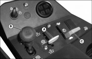
2. Move Mow/Transport lever (A) to the TRANSPORT position.
3. Pull Raise/Lower lever (B) rearward to raise cutting reels.
4. Move throttle lever (C) all the way forward to the FAST position.
To Travel Forward:
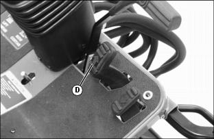
1. Depress speed control pedal (D) down to travel forward. The farther the pedal is pushed down the faster the mower will travel.
2. Remove foot from pedal to return to the NEUTRAL position and greensmower will stop.
To Travel in Reverse:
1. Allow speed control pedal (D) to slowly return to the NEUTRAL position to stop forward travel.
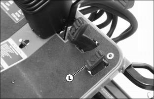
2. Depress speed control pedal (E) down to travel in reverse. The farther the pedal is pushed down, the faster the mower will travel.
3. Remove foot from pedal to return to the NEUTRAL position and greensmower will stop.
Using Free-Wheeling Tow Valve
IMPORTANT: Avoid damage! Transmission damage may occur if the machine is moved or towed incorrectly: |
When movement of greensmower is required without starting the engine, use the free-wheeling tow valve.
1. Stop engine and remove key.
3. Lift and secure operator seat in the raised position.
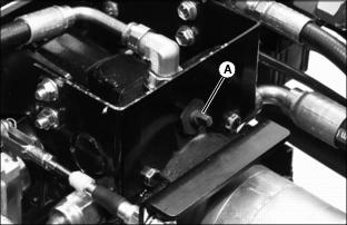
4. Turn free-wheeling tow valve (A) counterclockwise approximately two revolutions.
7. Push greensmower to desired location.
8. Turn free-wheeling tow valve (A) clockwise approximately two revolutions to the operating position.
Transporting the Greensmower
IMPORTANT: Avoid damage! Transmission damage may occur if the machine is moved or towed incorrectly: |
NOTE: Use a heavy-duty trailer designed to carry 909 kg (2000 lb), or a truck box to transport the machine.
2. Secure the cowling to the machine at the front to prevent the hood opening accidentally during transporting.
4. Lower the cutting units to the deck.
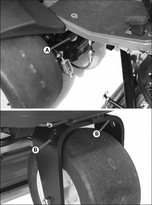
5. Secure machine to trailer with straps, chains, or cables.
· Attach the tie downs to slots (A) provided on both sides of the operator's station in the main frame and slots (B) on both sides of the rear wheel yoke.
6. Use accessory lights and devices when transporting the machine on a road or highway to provide adequate warning to operators of other vehicles. Check local, state, provincial, or federal laws.