
Operating - Cutting Units
Adjusting Bed Knife-to-Reel
IMPORTANT: Avoid damage! Adjust bed knife-to-reel by lowering and raising the bed knife evenly. Do not adjust more than one flat on the adjuster nut at a time, alternating side to side. |
1. Remove cutting reels from greensmower.
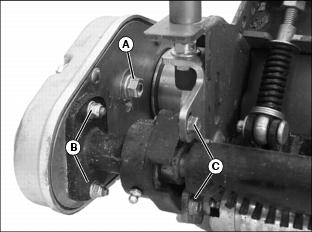
2. Position cutting unit upright on workbench as shown.
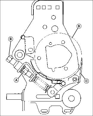
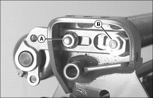
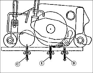
3. Loosen jam nut (A) on both sides of cutting unit and turn bed knife tower adjuster (B) counterclockwise until bed knife (C) is tight against cutting reel (D).
4. Slowly tighten tower adjuster (B) clockwise, alternating from side to side until bed knife begins to pull away from the cutting reel. Cutting reel should rotate freely.
NOTE: Make sure that the final adjustment to the bed knife is pulling the bed knife away from the cutting reel.
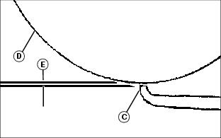
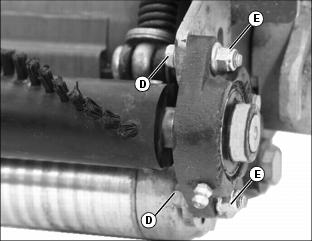
5. Alternately turn adjusters (B) no more than one flat at a time until bed knife to reel clearance (E) measures .025mm to .050mm (.001 in. to .002 in.).
6. Tighten jam nuts (A). Check the bed knife-to-reel clearance (E). Adjust again if necessary.
Adjusting Height-of-Cut Range
Adjust front roller brackets for the height of cut (HOC) range desired.
1. Select height-of-cut (HOC) adjustment range by adjusting the position of both front roller brackets.
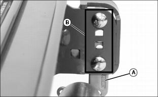
2. Align roller bracket (A) and cutting unit frame adjustment holes (B) on each side of the cutting unit to determine the HOC adjustment range.
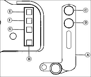
3. Refer to chart for desired setting.
0-6.351 |
|||
1
This setting is used when the diameter of the cutting reel has worn down to 120mm (4.7 in.) or less. |
Adjusting Front Roller Parallel with Bed Knife
NOTE: Use of a bench plate or a two or three bolt height-of-cut gauge bar is recommended when adjusting front roller parallel with the bed knife.
Always adjust bed knife-to-reel before adjusting front roller for parallelism.
Always make parallelism adjustment after adjusting front roller height of cut range.
Parallelism Adjustment with Bench Plate
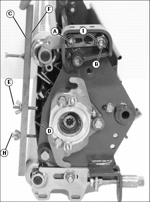
1. Position cutting unit upright on flat surface or workbench.

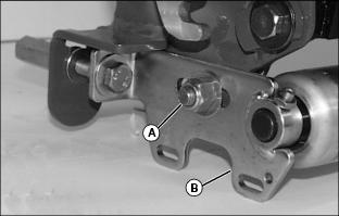
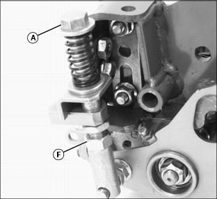
2. Loosen hex nut (A) and hex nut (B) on the left roller bracket.
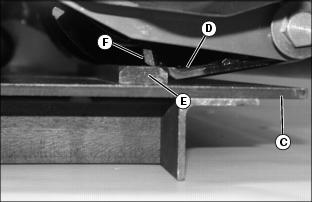
3. Set bench plate on a level surface. Set cutting unit on top of bench plate (C). Bed knife (D) must rest firmly against plate stop (E) with cutting reel blade (F) on top of plate stop.
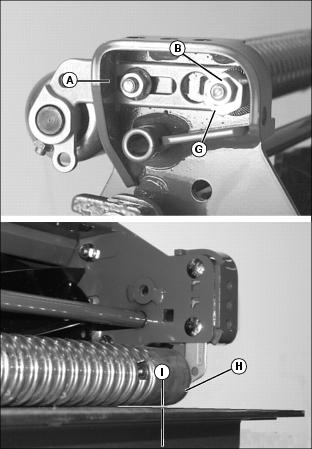
4. Rotate eccentric adjuster (G) until the front roller (H) sits flat and parallel with the bench plate. Gap (I) should not exceed 0.050mm (0.002 in.) maximum.
5. Tighten left roller bracket hex nut (A).
6. Tighten left roller bracket hex lock nut (B).
Parallelism Adjustment with HOC Gauge Bar
1. Position cutting unit upright on flat surface or workbench.
2. Loosen hex nut (A) and hex nut (B) on the left roller bracket.
NOTE: HOC gauge bar should not contact the bottom of the rear roller.
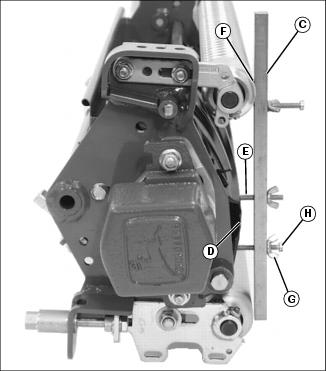
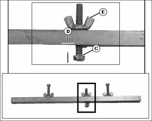
3. Rest HOC gauge bar (C) approximately 51mm (2 in.) from the RIGHT end of the bed knife (D).
4. Hook the center gauge screw (E) on the edge of the bed knife. Hold end of gauge bar against the bottom of front roller (F).
5. Loosen wing nut (G). Turn lower gauge screw (H) clockwise until top of screw makes contact with flat edge of bed knife.
NOTE: HOC gauge bar should not contact the bottom of the rear roller.
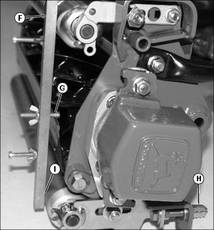
7. Rest HOC gauge bar (C) approximately 51mm (2 in.) from the LEFT end of the bed knife (D).
8. Hook the center gauge screw (E) on the edge of the bed knife. Hold end of gauge bar against the bottom of front roller (F).
9. Adjust position of front roller.
· Rotate eccentric adjuster (I) until top of lower gauge screw (H) makes contact with the bed knife.
10. Tighten left roller bracket hex nut (A).
11. Tighten left roller bracket hex lock nut (B).
12. Check adjustment using HOC gauge bar.
Adjusting Height of Cut
1. Position cutting unit upright, resting on the rear roller brackets.
2. Loosen lock nut (A) on both sides of rear roller just enough for the height-of-cut (HOC) bracket (B) to slide.
NOTE: If greensmower is equipped with the optional rear roller powered brush, the idler gear pivot lock nut and pivot bracket lock nuts must be loosened.
3. On the height-of-cut (HOC) gauge bar, set center adjustment bolt head (C) at the desired height of cut (D). Lock wing nut (E).
4. Rest HOC gauge bar against front roller (F) approximately 51mm (2 in.) from the end of the bed knife. Set the inside of the bolt head (G) against the edge of the bed knife.
5. Turn tower adjuster (H) until the rear roller (I) contacts the HOC gauge bar. Repeat for the other side of the cutting reel.
6. Check HOC adjustment setting from side to side and adjust if necessary. Tighten lock nut (A) on both sides of cutting unit.
Adjusting Cutting Unit Float Range
NOTE: All cutting unit lift chains must be adjusted equally.
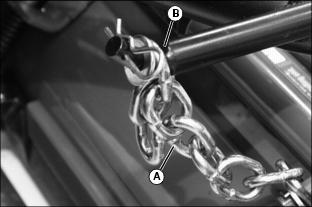
The cutting unit lift chains (A) can be adjusted if a different cutting unit float range is desired.
· attach the seventh chain link from the cutting unit to each cutting unit lift arm pin (B). Most normal mowing applications will use the seven chain link set up.
For applications with level surfaces-
· attach the sixth chain link from the cutting unit or less. This set up will provide more clearance when transporting to another work area, but will restrict float on greens with extreme undulations and contours.
For applications with extreme undulations-
· attach the eighth or ninth chain link from the cutting unit. Cutting unit ground clearance will be limited for transport.
Adjusting Reel Speed
IMPORTANT: Avoid damage! Operating the reels at a high speed can cause excessive bed knife and reel wear. Operate the reels at the appropriate reel speeds. |
1. Park the machine safely. (See Parking Safely in the SAFETY section.)
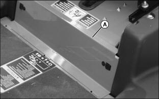
2. Open service access panel (A) below operator seat platform.
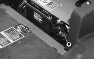
3. Locate reel speed control knob (B) behind service access panel.
NOTE: Reel speed can be adjusted depending on the type of application for the greensmower, which type of cutting units are used, and grass height and conditions.
It may be appropriate to reduce reel speed when cutting taller grass to prevent grass from being blown over and not being cut. Faster reel speeds with dry grass may cause grass clippings to be thrown over the grasscatcher.
5. Close service access panel.
Adjusting Greens and Turf Conditioner (GTC)
NOTE: Height Of Cut must be adjusted prior to adjusting the Greens and Turf Conditioner.
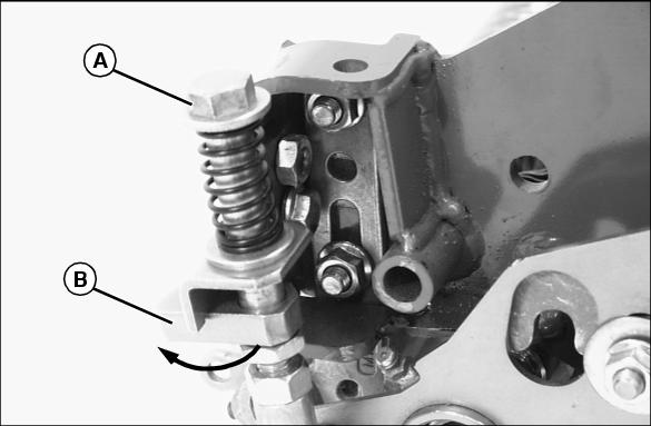
1. Press down on GTC adjuster bolts (A).
2. Swing adjuster stops (B) around toward the front of the cutting unit.
3. Position cutting unit to make height of cut adjustment.
4. Set GTC adjustment screw (C) on the gauge bar to the desired operating height.
· Adjustment screw (D) may need to be loosened so that the gauge bar can rest on both the front and rear rollers.
5. Place preset gauge bar on cutting unit. Hook height of cut screw (E) on bed knife. The ends should rest firmly on the front and rear rollers.
6. Loosen adjuster lock nut (F) on both ends of the cutting unit.
7. Turn adjuster bolt (A) to raise or lower GTC roll. Alternate from end to end until the teeth touch the screw on the gauge bar. Tighten adjuster lock nuts.
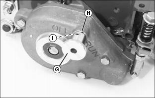
· Pull knob (G). Turn knob clockwise to the "RUN" position. Knob must engage detent (H).
· Turn knob counterclockwise to the "OFF" position. Knob must engage detent (I).
11. Disengage GTC adjuster stops:
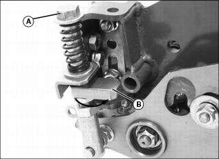
a. Press down on GTC adjuster bolts (A).
b. Swing adjuster stops (B) around toward the rear of the cutting unit.
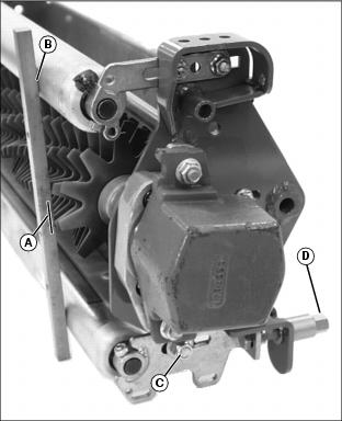
Adjusting (Optional) Rear Roller Powered Brush
NOTE: The brush cover is removed for photo clarity only.
1. Loosen idler gear pivot lock nut (A).
2. Loosen both pivot bracket lock nuts (B).
3. Loosen two flange head cap screws (C) on left side of cutting unit.
4. Loosen two flange head cap screws (D) and nylock nuts (E) on right side of cutting unit.
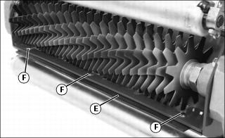
NOTE: The brush bristles should just barely clear the full length of the roller. The gap between the brush bristle tips and the roller should be approximately 1mm (1/32 in.).
5. Slide the roller brush up or down to adjust the roller.
6. Tighten flange head cap screws on left side of cutting unit and flange head cap screws and nylock nuts on right side of cutting unit.
7. Tighten both pivot bracket lock nuts and the idler gear pivot lock nut on the left side of cutting unit.
Operating and Adjusting (Optional) Vertical Cutters
NOTE: Vertical cutting units are intended for thatch removal and should not be set for ground engagement. The cutters should not be set to penetrate the soil.
For excess thatch conditions, several trips across the green may be necessary. Do not attempt to remove large amounts of thatch in a single cutting.
Operating Vertical Cutters
IMPORTANT: Avoid damage! Incorrect operation may cause excessive heating of the hydraulic oil. Do not operate cutting units in a "stalled" mode: |
1. Adjust mow speed limit to no more than 4.8 km/h (3 m.p.h.). The mow speed should be set properly to insure that the cutting reels do not stall out completely.
2. Set the initial adjustment of blade depth flush with the bottom of the rollers.
3. Increase the depth as needed to achieve desired results. Do not exceed a blade depth of 3mm (0.12 in.).
4. Measure the usable blade length of the cutting blades before making a vertical cutter adjustment. If usable blade length is less than the desired cutting depth, replace blades before continuing.
Adjusting Cutting Depth
1. Mark the desired cutting depth (A) on a gauge bar (B).
2. Place the gauge bar across the front and rear rollers approximately 50mm (2 in.) in from the end of the rollers.
3. Loosen lock nut (C) on each side of the cutting unit.
4. Adjust position of rear roller.
· Turn each tower adjuster (D) until leading edge of vertical cutting blade aligns with the cutting depth mark on the gauge bar.
· Rotate cutting reel back and forth to ensure blade tip does not extend beyond the depth mark.
· Check both ends of cutting reel until they are adjusted to the same setting.
· If the vertical cutter cannot be adjusted because of wear, replace the blades and then adjust to the correct depth.
NOTE: Adjustment of rubber flap height will depend on turf conditions.
· On short turf, lower the flap to prevent material from flying out the rear of the cutting unit.
· On turf with a lot of thatch, raise the flap to allow the removed thatch to exit out the rear of the cutting unit.
6. Adjust cutting unit rubber flap (E).
· Loosen three carriage bolts (F) and hex nuts.
· Adjust the flap approximately 13mm (1/2 in.) up from the bottom of the rollers.
7. Repeat procedure for other cutting units.
Operating Greens and Turf Conditioner
The conditioner process involves shallow vertical cutting. The blades are adjusted to cut runners and lift horizontal leaf material. It is important that frequent and thorough observations be performed or stress to the plants may occur. Make adjustments as necessary.
NOTE: The initial setting should be the same as Height Of Cut to prevent damage to the turf.
For a deeper cut, set approximately 0.79mm (.032 in.) below Height Of Cut.
1. Set the GTC blades the same height as the Height of Cut when conditioning greens for the first time.
2. While cutting with GTC, closely examine each green for any inconsistencies or appearance of over-aggressiveness. Decrease GTC penetration if necessary.
3. Check each green 1-2 hours after cutting. Look for any tendency toward a yellow or brown tint. This indicates over-stress.
4. If visible stress is observed, decrease GTC penetration to 0.39mm (0.016 in.) for next cutting.
5. Continue cutting/conditioning at this setting for three to five days. Check frequently for stress.
6. If no stress is observed, increase GTC penetration by 0.25mm (0.010 in.). Check for obvious over-aggressiveness. Observe for two to three days, watching for signs of stress.
7. Mow with GTC at this setting until stress becomes visible. Back off the GTC adjusted penetration by 0.25mm (0.010 in.).
NOTE: Stress is a cumulative result of many factors such as irrigation, temperature, humidity, chemical application, disease and thatch.
Conditioning aggressiveness will require adjustment and monitoring as these factors vary.
Conditioning frequency may also need to be reduced in some cases.
Engaging Reel Drive
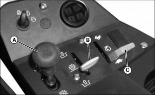
1. Pull Raise/Lower lever (A) rearward to raise cutting units.
NOTE: If the cutting units are lowered to the ground before the Mow/Transport lever is moved to the MOW position, the cutting reels will not rotate. Raise the cutting units before continuing with procedure.
2. Move the Mow/Transport lever (B) forward to the MOW position.
3. Move the throttle lever (C) forward to the FAST position.
4. Slowly begin forward travel.
NOTE: The front cutting units will lower to the ground before the center cutting unit.
Moving the Mow/Transport lever to the MOW position activates a switch so the cutting units automatically engage when lowered.
5. Push Raise/Lower lever forward to lower cutting units and start cutting reel rotation.
6. Pull back the Raise/Lower lever to raise the cutting units to transport lift height and automatically stop reel rotation.
Emergency Stopping - Cutting Reels
NOTE: There are two methods of stopping reel rotation in case of an emergency.
· Depress the park brake pedal and cutting reel rotation will stop.
· Move the Mow/Transport lever to the TRANSPORT position and cutting reel rotation will stop.
To begin cutting reel rotation:
· If the park brake was depressed, raise and lower cutting units.
· If the Mow/Transport lever was moved to TRANSPORT, move the Mow/Transport lever to the MOW position. Then raise and lower the cutting units.
Removing and Emptying Grasscatchers
NOTE: Remove center grasscatcher from left side of greensmower.
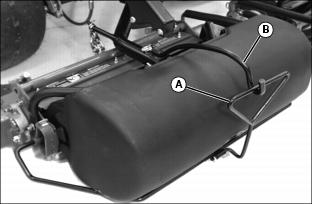
1. Raise and remove link handle (A) from catcher bracket support hook (B).
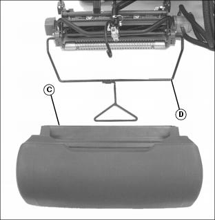
2. Remove grasscatcher (C) from frame assembly (D) and empty.