
Service Transmission
Hydraulic Oil
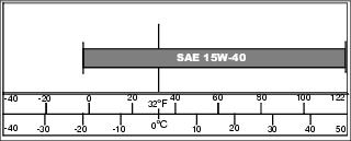
Use the following oil viscosity based on the air temperature range. Operating outside of the recommended oil air temperature range may cause premature hydrostatic transmission failure.
The following oil is recommended:
· JD Plus 50 15W-40 Synthetic Blend
· API Service Classification SG or higher
Checking Hydraulic Oil Level
IMPORTANT: Avoid damage! Check oil level in reservoir tank when oil is cold. Do not overfill oil reservoir tank. Oil will expand during operation and could overflow. |
1. Park machine safely on a level surface. (Refer to Parking Safely in SAFETY section.)
2. Lift thigh pad and latch in raised position.
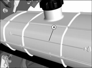
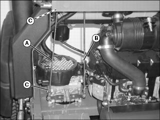
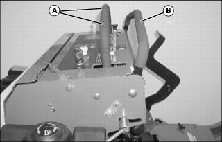
3. Hydraulic oil level should be at full mark (A).
· If oil is low, add oil to bring oil level no higher than full mark.
· If oil is above full mark, drain oil to proper level.
Changing Hydraulic Oil and Filter
1. Park machine safely. (Refer to Parking Safely in the SAFETY section.)
2. Allow engine and hydraulic oil reservoir to cool.
3. Lift thigh pad and latch in raised position.
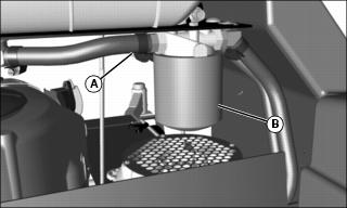
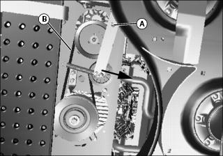
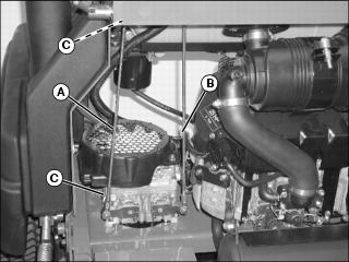
4. Disconnect filter inlet line (A).
NOTE: Place drain pan directly under filter head.
5. Allow hydraulic oil to drain into a drain pan with a capacity of at least 9.5 L (2.5 gal).
6. Turn oil filter (B) counterclockwise to remove.
7. Apply a film of clean hydraulic oil to gasket of new filter.
8. Install new filter. Turn filter clockwise until gasket makes contact with mounting surface. Tighten 1/2 to 3/4 turn after gasket contact.
9. Connect filter inlet line (A).
IMPORTANT: Avoid damage! Do not add oil beyond full mark. Oil capacity after draining may be less than dry fill capacity. Check oil level before filling completely. |
NOTE: Dry fill capacity for hydraulic system is 8.7 L (9.3 qt).
10. Fill oil reservoir with approximately 7.5 L (8.0 qt) of oil and tighten filler cap.
12. Move throttle lever to the fast position.
14. Cycle motion control levers forward and rearward several times. Check for leaks around filter.
15. Stop engine. Check oil level. Add oil as necessary to bring oil level to full mark on reservoir.
Cleaning Hydraulic Oil Pump Cooling Fins
IMPORTANT: Avoid damage! To ensure proper cooling, keep the cooling fins clean at all times. Operating the machine with obstructed cooling fins could cause damage due to overheating. |
1. Park machine safely. (See Parking Safely in the SAFETY section.)
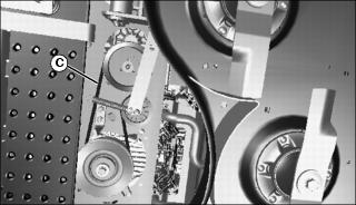
2. Clean hydraulic oil pump cooling fins (lower section of pump) (A) with a rag, brush or compressed air.
3. Clean area around hydraulic pump and frame.
Checking and Replacing Pump Traction Drive Belt
NOTE: The traction drive belt will not require a tension adjustment. Belt is self-adjusted using a spring tensioner.
Checking Traction Drive Belt
1. Park machine safely. (See Parking Safely in the SAFETY section.)
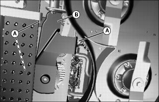
3. Remove belt shield (B) to access drive belts.
4. Inspect belt (C) for excessive wear, damage or stretching.
Removing Traction Drive Belt
1. Park machine safely. (See Parking Safely in the SAFETY section.)
2. Remove mower deck drive belt. See Replacing Mower Deck Drive Belt in the SERVICE MOWER section.
3. Insert a 1/2-inch drive ratchet or breaker bar in square hole (A).
4. Rotate tension idler pulley arm to remove tension from drive belt (B).
5. While holding idler pulley arm, remove traction drive belt (B).
Installing Traction Drive Belt
1. Use a 1/2-inch drive ratchet or breaker bar to rotate idler pulley arm as shown above and hold in place.
2. Install traction drive belt on drive sheaves.
3. Slowly allow idler arm to rotate into belt
Checking and Adjusting for Transmission Neutral Creep
NOTE: Check and adjust motion control linkages with the machine parked on a hard, level surface.
Checking Motion Control Linkages
1. Raise rear of machine with safe lifting device.
· Support with wood blocks or jackstands.
· Rear drive wheels must have the ability to rotate freely.
· If it is necessary to run an engine in an enclosed area, use an exhaust pipe extension to remove the fumes. |
3. Set throttle lever to the fast position.
5. If the rear drive wheels begin to creep, an adjustment is required.
Adjusting Motion Control Linkages
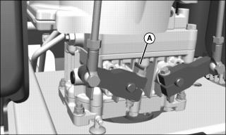
2. Locate right (A) and left (B) motion control linkages.
NOTE: If wheel rotates rearward, shorten linkage. If wheel rotates forward, lengthen linkage.
3. Adjust the appropriate linkage as follows:
a. Loosen jam nuts (C) on both ends of linkage.
b. Rotate center link in appropriate direction.
4. With the rear of machine supported on blocks, start engine and set throttle to fast position.
5. If wheels rotate, repeat adjustment.
6. Stand on operator's platform.
7. Move both motion control levers completely rearward and release. Move both motion control levers completely forward and release.
8. The levers should return back to the neutral position and the drive wheels must stop completely. If a drive wheel does not completely stop rotating, readjust as outlined above.
Checking and Adjusting Tracking
· If it is necessary to run an engine in an enclosed area, use an exhaust pipe extension to remove the fumes. |
NOTE: Check and adjust tracking on a hard, level surface.
Checking Transmission Tracking
1. Inflate tires evenly to correct pressure.
2. Start engine and run until it reaches normal operating temperature.
3. Move machine to an open, level area for operation.
4. Drive machine forward, pushing both control levers (A) all the way to speed control bar (B).
5. If machine does not drive in a straight line, an adjustment is required.
Adjusting Transmission Tracking
1. Park machine safely. (See Parking Safely in the SAFETY section.)
2. Locate right (A) and left (B) motion control linkages.
NOTE: If wheel rotates rearward, shorten linkage. If wheel rotates forward, lengthen linkage.
3. Adjust the appropriate linkage as follows:
a. Loosen jam nuts (C) on both ends of linkage.
b. Rotate center link in appropriate direction.
4. Repeat the previous step as necessary to adjust the tracking.
5. Check and adjust creep as necessary. (See Checking and Adjusting Creep in this section.)
Adjusting Forward and Reverse Speeds
Adjusting Forward Speed
1. Park machine safely. (See Parking Safely in the SAFETY section.)
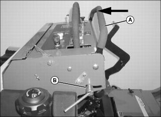
Picture Note: Arrow shows direction of speed control bar (A) movement to decrease forward speed.
2. Loosen lock lever (B) on speed control bar (A).
· To decrease forward speed, pull speed control bar (A) back toward the operator's station.
· To increase forward speed, push speed control bar (A) forward (away from operator's station).