
Service Cutting Units
Avoid Injury From Contacting Blades

Removing and Installing Cutting Units
Removing Cutting Units
1. Park the vehicle safely. (See Park Safely in the SAFETY section.)
NOTE: Identify which chain link is installed to the lift arm so lift chain can be installed correctly.
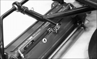
2. Disconnect lift chains (A) from lift arms.
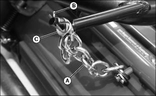
· Remove spring locking pin (B) and flat washer (C).
· Remove chain from lift arm pin.
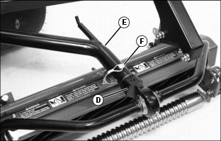
3. Disconnect yoke (D) from lift arm (E).
· Roll cutting unit forward away from lift arm.
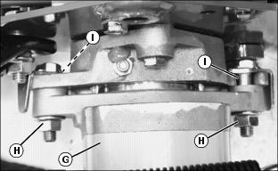
4. Remove hydraulic motor (G).
· Loosen locking assembly hardware (H).
· Rotate motor from reel bearing housing slots (I).
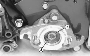
5. Inspect inside of reel bearing housing (J) for grease. Add John Deere Special Purpose HD Cornhead Grease to housing if additional lubrication is needed.
6. Check splined motor/reel coupling (K) for wear. Replace if necessary. Make sure coupling is lubricated with grease and remains in position on reel shaft.
7. Repeat procedure for other cutting units if necessary.
Installing Cutting Units
NOTE: Center cutting unit has the upstop bracket. Right front cutting unit has the steering limiter bracket.
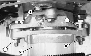
1. Install hydraulic motor (G) onto the reel bearing housing.
· Align splined reel coupling with splined motor drive shaft.
· Align locking assembly hardware with reel bearing housing slots (I).
· Tighten assembly locknuts (H).
NOTE: Yoke with steering limiter bracket must be installed to the right front lift arm.
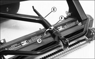
2. Install yoke (D) to lift arm (E).
3. Align yoke pin and lift arm mounting holes.
4. Fasten cutting reel in position with quick-lock pin (F).
NOTE: The lift chain can be installed to different links to adjust cutting unit lift height.
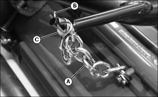
5. Install lift chain (A) onto lift arm pin. Make sure chain is not kinked.
6. Install flat washer (C) and spring locking pin (B).
7. Repeat procedure for other cutting units if necessary.
Mounting Electric Motor and Gear Case to Cutting Unit
1. Park the vehicle safely. (See Park Safely in the SAFETY section.)
2. Lower cutting units to the ground.
3. Move mow-transport lever to the TRANSPORT position.
4. Turn key switch to the STOP position and set park brake.
NOTE: Mark electrical connectors before removing to ensure correct installation.
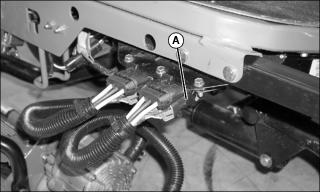
Picture Note: Left-Front Reel Motor Connector Shown
5. Disconnect electric reel motor harness connector (A).
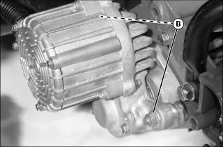
6. Loosen two reel motor mounting lock nuts (B).
7. Rotate assembly a few degrees counterclockwise and pull reel motor straight away from the cutting unit to remove.
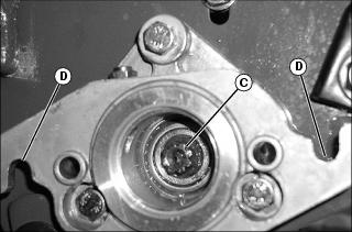
8. Fill housing cavity (C) with John Deere Cutting Unit Grease or NLGI Grade 0 Grease.
9. Set motor in place. Rotate clockwise until attaching cap screws are seated in reel housing slots (D).
10. Tighten cap screws securely.
Removing Cutting Unit Yokes
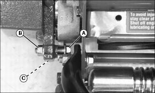
1. Remove flange head bolt (A), lock nut (B) and two pivot bushings (C) from each end of cutting unit yoke.
2. Install in reverse order of removal.
Removing and Installing Front Roller
Removing Front Roller
1. Remove cutting unit from greensmower.
2. Position cutting unit upright on a flat surface or workbench.
3. Remove hardware from left roller bracket.
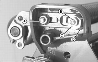
· Remove flange nut (A) and carriage bolt.
· Remove lock nut (B), eccentric adjuster (C), serrated washer (D) and carriage bolt.
4. Remove hardware from right roller bracket.
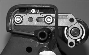
· Remove flange nuts (E) and carriage bolts.
5. Remove roller and bracket assembly from cutting unit frame.
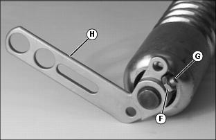
6. Loosen jam nut (F) and set screw (G) to remove bracket (H) from each bearing spindle shaft end.
Installing Front Roller
NOTE: Roller brackets are offset. For standard use, the bracket should be installed to the roller with the offset to the rear of the base cutting unit to allow close proximity of front roller to rear roller. If Greens Tender Conditioner (GTC) is being installed, offset should be to the front to allow the GTC to be installed behind the front roller.
Install the roller bracket with the larger holes and adjustment slot on the left side of the cutting unit.
The roller bearing spindle shaft has holes drilled in each end. Do not tighten set screws near the holes.
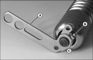
Picture Note: Photo shows left roller bracket being installed.
1. Install roller brackets (A) onto each bearing spindle shaft end.
2. Install set screws (B) and lock nuts (C) loosely. Do not tighten.
3. Select Height-of-Cut (HOC) adjustment range.
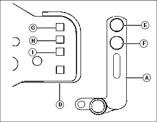
· Alignment of roller bracket (A) and cutting unit frame (D) adjustment holes will determine HOC adjustment range.
· Refer to chart for desired setting.
0-6.531 |
|||
1
This setting is used when the diameter of the cutting reel has worn down to 120 mm (4.7") or less. |
4. Slide assembly roller brackets into cutting unit frame slots.
5. Align selected HOC adjustment holes.
NOTE: Install carriage bolts from the inside.
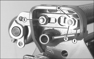
6. Fasten bottom of left roller bracket to frame using one M8 x 20 carriage bolt and one M8 flange nut (E).
NOTE: Install serrated washer with cupped side facing cutting unit frame.
7. Fasten top of left roller bracket to frame using one M8 x 40 carriage bolt, one serrated washer (F), one eccentric adjuster (G) and one M8 lock nut (H).
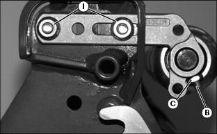
8. Fasten right roller bracket to frame using two M8 x 20 carriage bolts and two M8 flange nuts (I).
NOTE: Make sure the roller bracket set screw locations are not aligned with the holes in each bearing spindle shaft end. Set screws must engage the bearing spindle shaft at each end.
9. Center front roller. Tighten set screws (B) and jam nuts (C) on both roller brackets.
10. Tighten roller bracket attaching hardware.
11. Adjust front roller for parallelism.
Removing and Installing Rear Roller
Removing Rear Roller
1. Remove cutting unit from greensmower.
2. Position cutting unit with bottom side up on a flat surface or workbench.
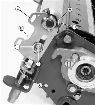
3. On each side of rear roller, loosen jam nut (A) and set screw (B).
4. Loosen jam nut (C) on each adjuster tower.
5. Remove carriage bolt (D), flat washer (E) and lock nut (F) attaching each height-of-cut (HOC) adjustment bracket (G) to the cutting unit frame.
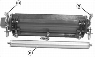
6. Move height-of-cut (HOC) brackets (G) away from each bearing spindle shaft end.
Installing Rear Roller
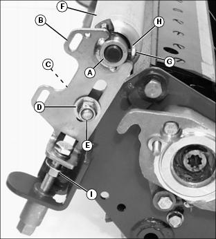
1. Install roller bearing spindle shafts (A) into each height-of-cut (HOC) bracket (B).
2. Install both height-of-cut brackets to cutting unit frame.
NOTE: Install carriage bolts from the inside.
3. Install carriage bolt (C), flat washer (D) and lock nut (E).
5. Center rear roller (F) inside HOC brackets.
6. Tighten set screws (G) and jam nuts (H).
7. Loosen lock nuts (E) approximately 1/4 turn.
8. Tighten jam nut (I) on each adjuster tower.
Replacing Bed Knife
Removing Bed Knife
1. Remove the cutting unit from greensmower.
2. Position cutting unit with the bottom side down on a flat surface or workbench.
3. Relieve tension from bed knife tension springs on both sides of cutting unit.
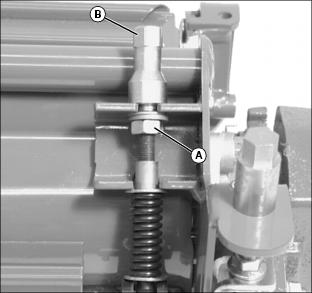
· Turn jam nuts (A) counterclockwise until springs are completely compressed.
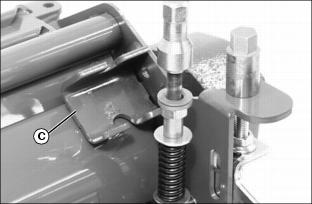
5. Rotate each adjustment assembly away from reel housing bracket (C).
6. Rotate cutting unit and position with bottom side up on flat surface or workbench as shown.
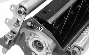
7. Remove shoulder bolt (D) from each end of cutting unit.
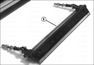
8. Slide bed knife assembly (E) out of the cutting unit housing.
9. If original bed knife is to be used again, grind the bed knife. (See Grinding Reel and Bed Knife in this section.)
Installing Bed Knife
1. Remove and discard thirteen screws attaching bed knife to assembly support. Discard bed knife.
2. The bed knife must be ground before installing in machine. (See Grinding Reel and Bed Knife in this section.)
NOTE: Remove debris, corrosion, and rust from bottom surface of bed knife support.
3. Install bed knife using new screws. Alternate tightening by starting with center screws and working out to the ends. Tighten screws to 7 N·m (62 lb-in).
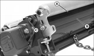
4. Slide bed knife and support assembly (A) into position inside locator shoe (B).
5. Install both shoulder bolts (C). Tighten hardware to 55 N·m (40 lb-ft).
6. Position cutting unit with bottom side down on flat surface or workbench.
7. Install each adjustment assembly inside housing mounting bracket.
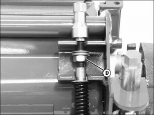
· Restore bed knife spring tension by turning jam nuts (D) clockwise. Turn jam nuts only midway up the threaded adjustment.
11. Check height-of-cut and adjust as necessary.
Grinding Reel and Bed Knife
Reel and Bed Knife Relationship
Reel mowers are precision machines requiring daily maintenance to maintain the well-groomed appearance of turfgrass. The scissor-like shearing action, that only a reel mower is capable of achieving, is only possible if the reel and bed knife are sharp and the reel-to-bed knife clearance is maintained.
Close examination of the reel-to-bed knife relationship reveals two square edges passing one another with approximately 0.051 mm (0.002 in.) clearance. There are several reasons why this clearance is necessary.
· When the reel is allowed to contact the bed knife, the square (sharp) edges of the reel and bed knife will roll over, becoming dull.
· Contact between the reel and bed knife generates heat. Heat generated through this contact will distort the shape of the bed knife. Distortion causes the bed knife to draw closer to the reel, resulting in more rollover of the cutting surfaces and more heat generated in the bed knife.
· Drag produced by an improperly adjusted cutting unit may result in an unacceptable clip ratio, undue strain on drive mechanisms and premature wear of the cutting unit.
Reasons for Grinding
· To restore the cylindrical shape of a reel that has become cone-shaped due to improper adjustment of the reel-to-bed knife clearance or worn reel bearings.
· To restore the edge when the grass is not being cut across the entire length of the bed knife, evidenced by streaks of grass left after the mower has passed. Usually the result of nicked blades caused by hitting foreign objects in the grass.
· To restore the edge when the lack of frequent backlapping allowed the edge to be rounded beyond the capability of the backlapping procedure to restore the edge.
· To restore the edge when the reel-to-bed knife clearance has been improperly adjusted (reel contacting bed knife).
Cutting action begins as the bed knife positions the grass to be cut at the cutting edge. The reel then pulls the grass toward the bed knife where it is sheared by the cutting edges as they pass one another.
In order for the grass to be cut at the proper height, it must contact the bed knife at the cutting edge. This is accomplished by grinding a 5° relief angle on the front face of the bed knife. Without a relief angle, the blade of grass will contact the lower edge of the bed knife and be bent over at too much of an angle prior to being cut. In the case of mowing greens, where very small cuts are being taken, the reel may not capture the grass at all, and no grass will be cut.
Although some spin grinding machine manufacturers say backlapping is not necessary, John Deere recommends backlapping after spin grinding to remove burrs and rough edges left from the spin grinding procedure. Backlapping produces a honed edge that will cut the grass evenly and leave the tops of the grass with clean, straight edges.
It is important to note, dull cutting edges will tear rather than shear the grass drawn into the bed knife. This will shock the grass plant and retard its growth.
Grinding the Bed Knife
NOTE: Bed knife and support assembly must be ground as a complete unit.

1. When grinding the bed knife, it is important to have a 6.5° relief angle on the top surface (A) and a 5° relief angle on the front surface (B).
2. Put entire bed knife support and bed knife in a suitable grinder and grind until material is consistently removed from the entire length of the top and front surfaces of the bed knife.
Grinding the Reel

John Deere recommends relief grinding the reels after spin grinding for these reasons:
· Reduced blade contact area results in less friction, requiring less horsepower to drive the reel and increases fuel efficiency.
· Less time is required to backlap.
· Reduces pulling and tearing of the grass as the unit gets dull by use.
· Provides an area for backlapping compound to be trapped to more effectively backlap reels.
· Relief grinding removes metal from the trailing edge of the blade, forming an angle (relief angle) to reduce the contact area of the cutting edges.
· Because of the relief grind it is possible, with backlapping, to true a reel (make it round) if a blade is 0.025-0.051 mm (0.001-0.002 in.) too high.
Adjusting Cutting Unit Shield
NOTE: Keeping the shield close to the cutting blades improves the performance of the grass catcher in most conditions.
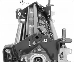
1. Loosen two bolts (A) and lock nuts on each side of cutting unit.
2. Raise or lower shield (B) to desired position.
· Maintain an approximate 1.5 mm (0.06 in.) clearance between the bottom of the shield and the top of the cutting blades.
Backlapping Cutting Units
The backlapping procedure is used to sharpen the cutting edges when grinding is not necessary. See GRINDING REEL AND BED KNIFE in this section to determine if grinding is necessary.
Backlapping, when compared to grinding, removes a very small amount of metal, requires less time and will effect a smooth, clean cut.
The backlapping procedure is accomplished by spinning the reel backward while applying special abrasive compounds to the reel. Usually, course compounds are used initially, followed by a finer abrasive for final honing. Recommended grits for fairways and roughs are 60, 80, and 120. Reel lapping compounds should not be toxic, oily or greasy.
The cutting unit should be inspected, backlapped, adjusted and checked daily for a uniform cut along the complete length of the bed knife. It is important that the adjustment allows the reel to turn freely without dragging against the bed knife. Metal-to-metal contact will generate heat, causing the reel to expand and intensifying the dragging that produces more heat. This cycle will quickly "shut down" the mower.
NOTE: To help maintain sharp edges required on cutting reels, bed knife-to-reel clearance should be checked before the backlapping function begins. The bed knife must be adjusted properly to ensure light, even contact over the length of the cutting blades.
Cutting reels are all backlapped at the same time.
1. Check bed knife-to-reel clearance on all three cutting reels. Adjust if necessary.
3. Move mow-transport lever to the TRANSPORT position.
5. Lower cutting units to the ground.
NOTE: Operator must be off the seat for the backlapping valve to function.
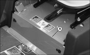
7. Open service access panel (A) below operator seat platform.
8. Locate backlapping control to the left of the battery.
· Position throttle lever between mid-range and SLOW idle.
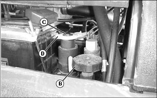
Picture Note: 2500A Model Shown
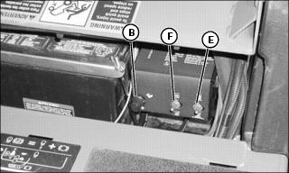
Picture Note: 2500E Model Shown
· Adjust reel speed control knob (B) fully counterclockwise.
2500A
NOTE: Forward-reverse control knob must be pulled up completely past first detent for the backlapping valve to function properly.
· Press in on the release button (C) at the center of the forward-reverse knob (D) and pull the knob out until it locks into the reverse position.
2500E
· Move mow-backlap switch (E) to BACKLAP position.
· Move forward-reverse switch (F) to REVERSE position.
12. Move the mow-transport lever to MOW position.
13. Activate raise-lower lever.
· Move and hold lever forward.
· When cutting reels begin turning in REVERSE, release lever.
NOTE: Adjust reel speed so that reel sharpening compound is not thrown off during the backlapping procedure.
14. Increase reel speed slightly, but not so fast that backlapping compound is thrown off.
15. Using a long-handled brush, carefully apply reel sharpening compound, uniformly, from one end of the cutting reel to the other. Repeat application in opposite direction. Allow cutting reel to continue running backwards until reel is quiet.

16. Periodically disengage cutting units by moving the mow-transport lever to the TRANSPORT position and turn key switch to the STOP position. Visually check blade appearance.
NOTE: 2500A - Forward-reverse control knob must be pushed down to restart engine.
2500E - Mow backlap switch must be moved to MOW to restart engine.
· Check for uniform clearance across entire bed knife. If clearance is not uniform, repeat backlapping procedure until clearance is uniform across entire bed knife.
Repeat process until the bedknife and reels are returned to a sharp condition.
IMPORTANT: Avoid damage! Do not operate cutting reels in the forward direction until reel sharpening compound is washed from the unit. Unless properly washed, the reels can be dulled by the compound. |
17. Use water to thoroughly wash off all reel sharpening compound while cutting reels are turning in reverse.
18. Adjust reel-to-bed knife clearance.
19. Move mow-transport lever to the TRANSPORT position.