
Installing
Installing Block Off Plate
48 and 52 in. Mower Decks
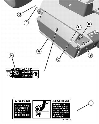
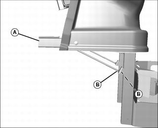
1. Install block off plate (A) on inside of outer tabs on support plate (B).
2. Install spring (C) on rod (D), with long end of spring through opening (E), and short end placed under block off plate onto deck. Place rod and spring through two tabs on support plate (B).
3. Secure rod in place with washer (F) and cotter pin (G).
4. If not already installed, install danger label (H) on top side of block off plate so that label can be read when block off plate is down.
NOTE: Warning label (I) is already on deck but is partially obscured with new block off plate. Position new label over the partially exposed portion of the existing label.
5. Install warning label (I) on mower deck.
61 in. Mower Decks
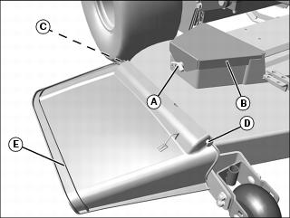
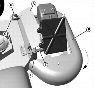
1. Remove knob (A) and belt cover (B).
2. Remove fastener (C) and rod (D), and remove mower discharge chute (E).
NOTE: Before drilling holes (H) in deck, be sure to mount blower housing so square tubing on blower housing mounts properly into square opening in support bracket (F).
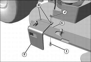
3. Install support bracket (F) onto deck support plate (G), mark holes (H), and remove support bracket (F) and drill two 11 mm (0.43 in.) holes (H) into deck.
4. Install support bracket and secure with two 10 mm flange bolts (I) and locknuts (J).
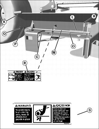
5. Install block off plate (K) on inside of outer tabs on support plate (G).
6. Install spring (L) on rod (M), with long end of spring through opening (N), and short end (O) placed under deflector plate onto deck, and place rod and spring through three tabs on support plate (G).
7. Secure rod in place with washer (P) and cotter pin (Q).
8. If not already installed, install danger label (R) on top side of block off plate so that label can be read when block off plate is down.
NOTE: Warning label (S) is already on deck but is partially obscured with new block off plate. Position new label over the partially exposed portion of the existing label.
9. Install warning label (S) on mower deck.
Installing Power Flow
48 and 52 in. Mower Decks
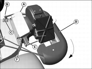
1. Raise deflector plate (A), and install rod end (B) of support frame in mounting bracket (C).
2. Rotate power flow (D) clockwise to place opposite end support frame end (E) flush onto plate (F).
3. Move tension lever (G) to release position.
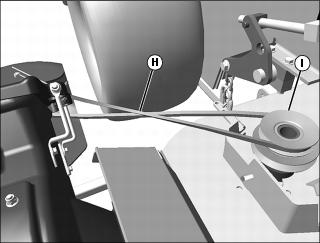
4. Install drive belt (H) to top sheave (I) with belt “V” in groove.

5. Verify correct drive belt installation. The drive belt must run:
a. from mower deck top sheave (I),
e. back to mower deck top sheave (I).
6. Move tension lever (G) to lock position.
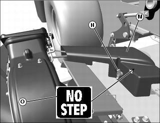
7. Install belt shield (M) over stud on welded deck sheave guard, and secure with washer and wing nut (N).
8. If not already installed, install “no step” label (O) onto top of belt shield.
61 in. Mower Decks
1. Raise block off plate (A), and install rod end (B) of support frame in front anti-scalp wheel mounting bracket (C).
2. Rotate power flow (D) clockwise to place opposite end support frame end (E) into plate (F) square opening.
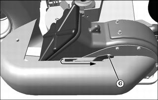
3. Move tension lever (G) to release position.
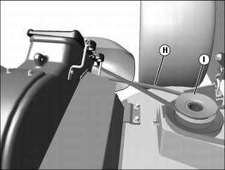
4. Install drive belt (H) to top sheave (I) with belt “V” in groove.
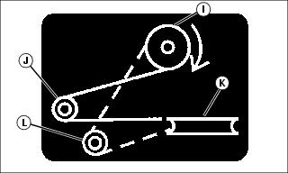
5. Verify correct drive belt installation. The drive belt must run:
a. from mower deck top sheave (I),
e. back to mower deck top sheave (I).
6. Move tension lever (G) to lock position.
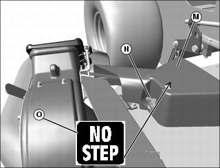
7. Install belt shield (M) over stud on welded deck sheave guard, and secure with washer and wing nut (N).
8. If not already installed, install “no step” label (O) onto top of belt shield.
Installing Upper Chute
1. Install power flow assembly on mower deck.
2. Install bagger assembly to rear of machine.
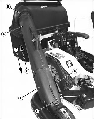
Picture Note: 61 in. deck shown
3. Insert round end of power flow chute (A) into hopper opening (B). Guide chute into hopper far enough upward (C) to provide clearance for connection to the power flow.
4. Lift and hold open exhaust door (D) on power flow.
5. Lower (E) chute assembly and slide square end of power flow chute (F) over power flow outlet.
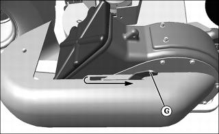
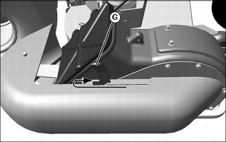
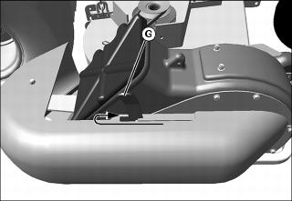
6. Secure strap hook (G) through hole on power flow.
7. Close and latch the hopper lid.
Installing Grass Bags
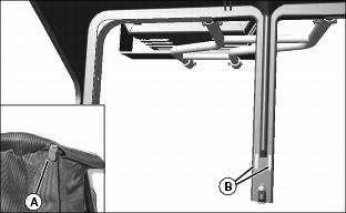
1. Install grass bags to hopper frame by inserting clip (A) into hole (B) in center frame bag support.
Installing Bagger Assembly
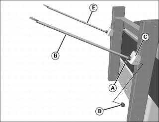
1. With locknut (A) installed on the end of rod (B), secure rod to bracket (C) on end of rear mounting bracket with second locknut (D). Repeat for opposite side (E).
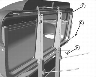
2. Install hopper (F) onto top of rear mounting bracket, and secure through holes with pin (G) and spring locking pin (H).
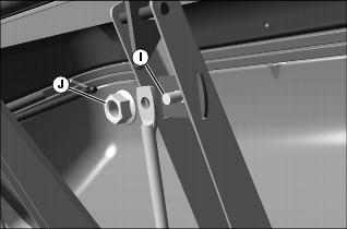
3. Rotate hopper downward, and secure other end of each support rod to the hopper support channel using M8x15 carriage bolt (I) and M8 flange nut (J). Tighten nuts completely.
Adjusting Hopper
NOTE: Machine must be parked on a level surface with tires inflated to the correct air pressure before adjusting the hopper.
2. Stand to the side of the hopper. Support frame (A) should be angled 2 - 3 degrees forward of level. Adjust hopper if necessary:
a. Loosen flange nuts (B) on hopper support rods.
b. Adjust nuts until support frame is angled slightly forward.