
Service Mower
Removing and Installing Mower Deck Foot Plate
Removing Foot Plate
1. Park machine safely. (See Parking Safely in the Safety section.)
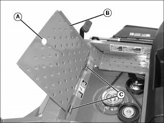
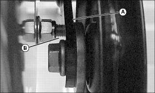
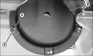
2. Pull foot plate (B) up using handle (A).
3. Lift foot plate in the direction shown to disengage hinge tabs (C) from holes in the front frame.
Installing Foot Plate
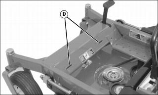
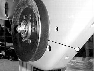
1. Insert hinge tabs on foot plate into holes (D) in the front frame.
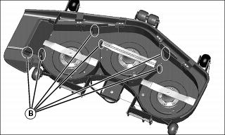
Removing and Installing Mower Deck Drive Belt Shields
Removing Belt Shields:
1. Park machine safely. (See Parking Safely in the SAFETY section.)
2. Lower mower deck to the lowest cutting height position.
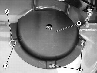
3. Remove belt shield locking rings (A).
4. Remove belt shields (B) by lifting corner of belt shield from drilled stud (C). Rotate shield counterclockwise to clear head pins (D).
Installing Belt Shields:
1. Install belt shields by rotating shield clockwise to engage head pins (D) and drilled stud (C).
2. Install belt shield locking rings (A).
Replacing Mower Deck Drive Belt
Removing Deck Drive Belt
1. Park machine safely. (See Parking Safely in the Safety section.)
2. Lower mower deck to the lowest cutting height position.
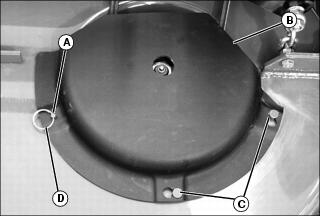
3. Remove belt shield locking rings (D).
4. Remove deck belt shields (B).
· Lift corner of belt shield from drilled stud (A). Rotate shield counterclockwise to clear head pins (C).
5. Remove mower deck foot plate.
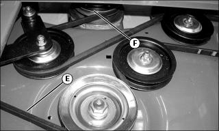
6. Remove deck drive belt (E).
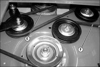
· Remove deck drive belt from upper jackshaft assembly sheave (F), spindle sheaves and idler pulleys.
· Loosen cap screw (H) enough to allow the idler arm weldment (I) to be raised and the belt slid under idler pulley (G).
· Remove deck drive belt from mower deck.
Installing Deck Drive Belt
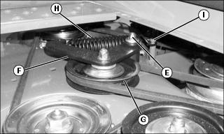
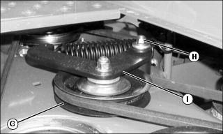
1. Raise the idler arm weldment (F) and slide the replacement belt under idler pulley (G).
3. Check to make sure the belt tension spring (H) is installed properly between the idler arm weldment (F) and stud (I).
NOTE: If necessary, see drive belt installation label on mower deck.
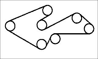
4. Install replacement drive belt as shown. Make sure drive belt is installed properly on the upper jackshaft assembly sheave, the mower deck idler pulleys and spindle sheaves.
5. Install both mower deck belt shields.
· Install belt shield locking rings.
6. Install mower deck foot plate.
7. Adjust mower deck to a desirable cutting height.
Checking and Adjusting Mule Drive Belt Tension
Checking Belt Tension
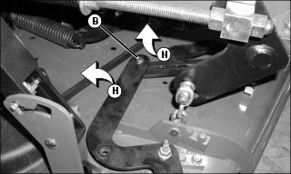
1. Check the mule drive idler arm (A) to see if it is contacting the bolt (B). If there is contact, adjust the mule drive belt tension.
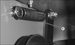
2. Check the extended length of the tensioning spring (C). If it is less than 16.6 cm (6-1/2 in.), adjust the mule drive belt tension.
Adjusting Belt Tension
1. Remove the mule drive belt from the fixed idler (D).
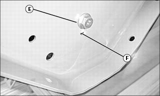
2. Loosen the bolt (E) on the fixed idler.
3. Lower the idler in the slot (F) approximately 6 mm (1/4 in.) and tighten bolt (E).
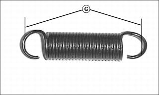
4. Install mule drive belt and verify that the idler arm does not contact bolt and that the length (G) of the installed tensioning spring is between 16.6-18.7 cm (6-1/2-7-1/4 in.).
5. Adjust idler again, if necessary.
NOTE: If proper belt tension is not achieved by adjusting the idler, the mule drive belt will need to be replaced.
Replacing Mule Drive Belt
Removing Mule Drive Belt
1. Park machine safely. (Refer to Parking Safely in the Safety section).
2. Remove belt shield locking rings (D).
· Lift corner of belt shield from drilled stud (A). Rotate shield counterclockwise to clear head pins (C).
4. Remove mower deck foot plate.
5. Release mower deck belt spring tension.
· Roll drive belt off of one spindle sheave.
NOTE: It is not necessary to remove the drive belt from the mower deck.
6. Remove mower deck belt (F) from upper jackshaft assembly sheave (E).
NOTE: Installation and removal of the mule drive belt is easier if the mower deck is placed in the lowest height-of-cut position.
7. Lower the mower deck to the 47 mm (1.5 in.) cutting height position.
8. Lift and secure operator's seat in the raised position.
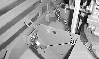
9. Unlatch rear grill by releasing latches (G) securing it to the machine.
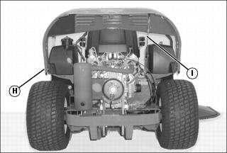
10. Raise rear grill (H) and securely support with prop rod (I).
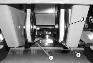
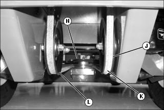
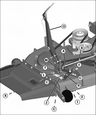
11. Remove mule drive belt (K) from idler sheave (J).
· Use an 18 mm ratchet and socket wrench to raise the idler sheave (L) and release belt spring tension.
· Roll mule drive belt (K) to the left and off the idler sheave (J).
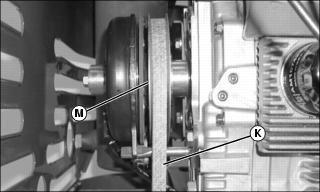
12. Remove mule drive belt (K) from the PTO clutch sheave (M).
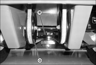
13. Remove mule drive belt from idler pulley (O) and jackshaft assembly sheave (N).
14. Remove mule drive belt from machine.
Installing Belt
1. Install replacement mule drive belt.
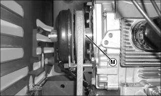
· Install drive belt onto the PTO clutch sheave (M).
· Install mule drive belt onto the jackshaft assembly sheave (N), and idler pulley (L).
2. Install mule drive belt (K) onto idler pulley (J).
· Installation of the drive belt is easier if an 18 mm ratchet and socket is used to raise idler sheave (L) and release belt spring tension.
· Roll drive belt onto idler pulley (J).
3. Lower the mower deck lift lever to the lowest cutting height position.
4. Install mower deck drive belt.
5. Install mower deck foot plate.
6. Install both mower deck belt shields.
· Install belt shield locking rings.
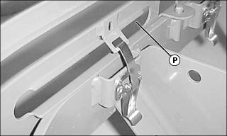
7. Lower rear grill and close latches (P) to secure.
8. Adjust mower deck to a desirable cutting height.
Mulch-On-Demand Mower Deck: Cleaning
NOTE: Routine cleaning of the mower deck will insure best baffle function and highest cut quality.
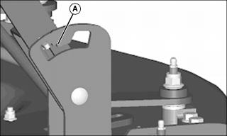
1. If the mower deck mode handle pawl is engaged in forward notch (A), the baffles will not close fully, and cut quality will degrade.
2. Park machine safely. (See Parking Safely in the Safety Section.)
3. Raise the mower deck to the transport position. (Also the 12.7 cm (5 in.) cutting height position.)
4. Raise front of machine with a safe lifting device.
· Support with jack stands and/or wooden blocks.
5. Clean grass clippings and debris from around Mulch-On-Demand linkage.
6. Clean underside of mower deck, particularly in critical areas (B).
7. If baffles still do not close fully, follow Adjusting Linkage procedure.
Mulch-On-Demand Mower Deck: Adjusting Linkage
NOTE: Clean mower deck to allow free movement of baffles.
1. Move deck mode lever into the side discharge position. See Operating Mulch-On-Demand Mower Deck.

2. Disconnect the extension spring (J) connected to the right outer baffle arm (H).
3. Loosen the five jam nuts (C) on links (A, I and L), and disconnect them from their respective arms at the rod end side.
4. Loosen the slider bushing bolt (B). Adjust the right inner baffle arm (N) until it makes contact with its stop point. Adjust the right outer baffle arm (H) until the right outer baffle makes contact with the right inner baffle. Tighten the slider bushing bolt (B).
5. Adjust the left outer baffle arm (D) until it makes contact with its stop point. Adjust the baffle link (A) to fit the left outer baffle arm. Secure baffle link (A) to left outer baffle arm (D) with the appropriate hardware and tighten the jam nut.
6. Adjust the left inner baffle arm (E) until it makes contact with the left outer baffle. Adjust the baffle link (A) to fit the left inner baffle arm. Secure baffle link (A) to left inner baffle arm (E) with the appropriate hardware and tighten the jam nut.
7. Adjust the discharge gate link (I) so that the discharge gate (K) is fully closed. Secure discharge gate link to discharge gate with the appropriate hardware and tighten the jam nut.
8. Install the handle link (L) on right outer baffle arm (H) and move the deck mode lever (O) to the side-discharge position.
9. Attach extension spring (J).
10. Move deck mode lever (O) into the mulch position Adjust handle link (L) so that the baffles and discharge gate are fully closed when the deck mode lever is latched into the rear most gate. Tighten the jam nuts on handle link (L).
11. Cycle the deck mode lever several times to make sure the baffles move freely and fully from mulch mode to side discharge mode. If baffles need further adjusting, adjust appropriate linkage.
Checking and Replacing Mower Blades
NOTE: Only replace blades. Never straighten or weld them.
Checking Mower Blades
1. Park machine safely. (See Parking Safely in the Safety Section).
2. Raise the mower deck to the transport position. (Also the 12.7 cm (5 in.) cutting height position.)
3. Raise front of machine with a safe lifting device.
· Support with jack stands and/or wooden blocks.
· Mower blades should be sharp and free of any damage.
· Inspect blades; sharpen/balance or replace as necessary.
Replacing Mower Blades
1. Use a wooden block to prevent mower blades from spinning.
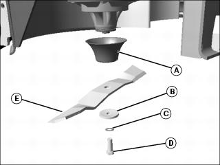
2. Remove screw (D), hardened washer (C), large concave blade washer (B), blade (E) and deflector cup (A).
· Blade wing must face toward top of mower deck.
IMPORTANT: Avoid damage! When installing the blade: · Make sure the blade is properly seated on the spindle. · Make sure the concave side of the large washer faces towards the blade. |
· Install deflector cup, hardened washer, blade, large concave blade washer, and cap screw.
· Tighten blade bolts to 122 N·m (90 lb-ft).
5. Adjust mower deck to a desirable cutting height.
Sharpening Blades
· Sharpen blades with grinder, hand file, or electric blade sharpener.
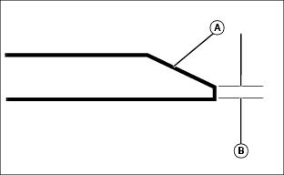
· Keep original bevel (A) when grinding.
· Blade should have 0.40 mm (1/64 in.) cutting edge (B) or less.
· Balance blades before installing.
Balancing Blades
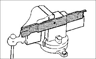
2. Put blade on nail in a vise. Turn blade to horizontal position.
3. Check balance. If blade is not balanced, heavy end of blade will drop.