
Service Transmission
Hydrostatic Transmission and Hydraulic Oil
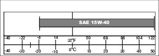
Use the following oil viscosity based on the air temperature range. Operating outside of the recommended oil air temperature range may cause premature hydrostatic transmission failure.
The following oil is preferred:
The following oil is also recommended:
The following oil is allowable:
• API Service Classification SG or higher
Cleaning Hydraulic Pump Cooling Fins
• Clear work area of bystanders. • Wear eye protection when using compressed air for cleaning purposes. |
IMPORTANT: Avoid damage! To ensure proper cooling, keep the cooling fins clean at all times. Operating the machine with obstructed cooling fins could cause damage due to overheating. |
1. Park machine safely. (See Parking Safely in the SAFETY section.)
2. Lift and secure operator seat in the raised position.
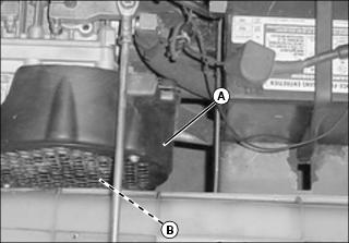
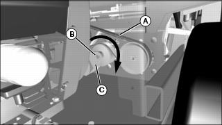
3. Remove fan guard cover (A) to access fan. Clean hydraulic pump cooling fins and fan (B) with a rag, brush, or compressed air.
5. Ensure seat latch is engaged.
Checking Hydraulic Oil Level
IMPORTANT: Avoid damage! Hot hydraulic oil will expand and show incorrect oil level. Check oil level: |
NOTE: Do not overfill oil reservoir tank. Oil will expand during operation and could overflow.
1. Park machine safely. (Refer to Parking Safely in Safety section.)
2. Lift and secure operator seat in the raised position.
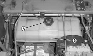
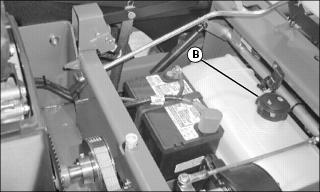
3. Thoroughly clean area around reservoir fill cap (A).
4. Visually check level of fluid. Fluid level should be even with the fill line (B) on the side of the tank.
5. To add oil, remove cap from the oil reservoir tank filler neck.
6. Install cap on filler neck.
Changing Hydraulic Oil and Filter
1. Park machine safely. (See Parking Safely in the SAFETY section.)
2. Allow engine and hydraulic oil reservoir to cool.
3. Lift and secure operator seat in the raised position.
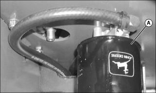
4. Turn transmission oil filter (A) counterclockwise to remove.
5. Allow transmission oil to drain into a drain pan with at least a 9.5 L (2.5 gal) capacity.
6. Apply a film of clean oil on gasket of new filter.
7. Install filter. Turn filter clockwise until gasket makes contact with the mounting surface. Tighten 1/2 to 3/4 turn after gasket contact.
8. Clean area around reservoir fill cap (B).
9. Remove cap from the oil reservoir tank filler neck.
10. Fill oil reservoir with approximately 7.6 L (2 gal) of oil.
12. Move throttle lever to the fast position.
14. Cycle motion control levers forward and rearward several times. Check for leaks around filter.
15. Stop the engine. Check oil level. Add oil as necessary.
Checking and Replacing Pump Drive Belt
NOTE: The transmission drive belt will not require a tension adjustment. Belt is self-adjusted using a spring tensioner.
Checking Belt
1. Stop engine and lock park brake.
2. Lift and secure operator seat in the raised position.
3. Inspect belt (A) for excessive wear, damage or stretching while in position on the transmission sheaves and drive belt tensioner sheave.
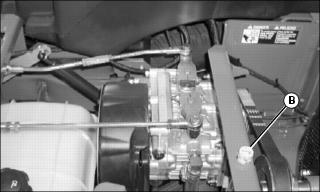
Replacing Belt
1. Place a 1/2-inch breaker bar into square hole (B) of idler bracket (C). Rotate idler bracket to remove tension from drive belt.
2. Remove belt from drive sheaves and idler sheave.
IMPORTANT: Avoid damage! Belt must be properly aligned with grooves in sheaves to prevent premature wear. |
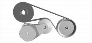
3. Install belt onto drive sheaves and idler sheave as shown.
NOTE: Idler tension requires no adjustment.
Checking and Adjusting Motion Control Linkages
Checking Motion Control Linkages
NOTE: Check and adjust motion control linkages with the machine parked on a hard, level surface.
1. Raise rear of machine with a safe lifting device.
• Support with wood blocks or jackstands.
• Rear drive wheels must have the ability to rotate freely.
2. Sit on operator’s seat and place both motion control levers in the neutral lock position.
4. Set throttle lever to the fast position.
6. If the rear drive wheels begin to creep, an adjustment is required.
Adjusting Motion Control Linkages
1. Stop engine and lock park brake.
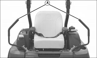
2. Move both motion control levers (A) to the neutral lock position.
3. Lift and secure operator seat in the raised position.
4. Activate operator seat safety switch (B).
• Clamp a wooden block to machine frame and across seat switch to activate seat switch.
6. Set throttle to the fast idle position.
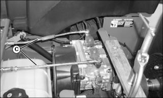
8. Locate left and right motion control linkages (C).
9. Be sure the right motion control lever is in the neutral lock position.
• The right drive wheel must not turn. If it does turn, adjust the motion control linkage:
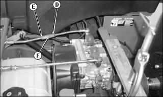
a. Loosen hex nuts (D and E) on each end of the center link (F).
b. Adjust center link (F) until the wheel stops rotating completely.
10. Move the right motion control lever completely rearward in the slot and release lever. The lever should return back to the neutral position (completely centered in the slot).
• The drive wheels must stop completely. If the drive wheel does not completely stop rotating, a damper mount adjustment is necessary:
• Adjust damper in slot as necessary; tighten nut to 20 N•m (15 ft-lb).
11. Move the right motion control lever completely forward and rearward in the slot and then back to the neutral lock position.
• The drive wheels must stop completely. If the drive wheel does not completely stop rotating, repeat steps 9 and 10.
12. Repeat procedure to adjust the left motion control linkage. Loosen jam nuts on both ends of linkage and turn linkage to adjust.
14. Move both motion control levers to the neutral lock position.